What is the Use of Reactors and Shunt Capacitor Banks?

Shunt capacitor banks are installed for a variety of reasons in industrial, distribution and transmission systems. A common thread to all installations is the question of what, if any series reactor should be installed with the capacitor bank.
Related Readings: Fundamentals of Capacitor Protection
Series reactors are used with capacitor banks for two main reasons:
- To dampen the effect of transients during capacitor switching, and to
- Control the natural frequency of the capacitor bank and system impedance to avoid resonance or to sink harmonic current.
This note is based on a realistic example and discusses the effect and consequences of different types of reactor.
Capacitor switching transients
When a capacitor bank is energised, the bank and the network are subject to transient voltage and current. The severity of the effect is determined by the size of the capacitor and the network impedance. The worst case occurs when a capacitor bank is energised close to a bank that is already connected. The inrush current into the newly connected bank (and out of the connected bank) is determined by the size of the capacitor bank and the inductance between the two banks. The larger the banks, and the smaller the inductance between banks, the higher will be the inrush current.
The frequency of the inrush current is determined by the ratio of capacitor bank reactance and the impedance between the banks. The smaller the impedance, the higher will be the frequency.
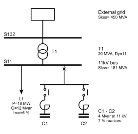
Consider the case shown in the following simplified single line diagram. An 11 kV substation is supplied via a 132 kV/11 kV transformer. At 11 kV, a load with moderately poor power factor is overloading the supply transformer. It is decided to compensate the load by means of 8 Mvar of reactive power, in two steps of 4 Mvar.
 |
| source: Nokian Capacitors |
If the only impedance between the two banks is that in the busbar and cabling between the banks, a very large, high frequency inrush current will flow between the banks, as shown in the figure below. In this case, with only some micro-henrys between the banks, a peak current of more than 120 times nominal current, at a frequency of more than 8 kHz can be expected.

Capacitor standards such as IEC 60871 and AS 2897 state that capacitors should be able to withstand inrush currents up to 100 times nominal. The standards suggest a lower value if banks are switched frequently. Large and high frequency inrush current can damage capacitors, circuit breakers and contactors.
Related Readings: Power Factor Correction in AC System
All connected equipment, and even remote substations are subject to voltage transients and may result in sporadic equipment malfunction or failure. To avoid this problem, it is common practice to insert inrush limiting reactors in series with the capacitor banks. In the diagram below, 150 micro-Henry reactors have been inserted in series with each bank.

The peak inrush current is now almost an order of magnitude smaller, at a much lower frequency, as can be seen from the trace below. From an inrush limiting perspective, this should be sufficient protection for the capacitor bank and associated equipment.
Voltage Distortion
Even if switching can be arranged in such a manner that no transient current occurs (such as promised by point of wave switching) due consideration must be given to the natural frequency of the network, and the effect of harmonic resonance. The traces below indicate the impedance of the network above, as seen from the 11 kV busbar.

It can be seen that the network presents high impedance at 250 Hz and 350 Hz, depending on whether one or both capacitor banks are energised. Even if the current distortion is low, very high voltage distortion can be expected as a result of harmonic currents flowing into this high impedance. In the chart below, it is seen that the voltage distortion (VTHD) at the 11 kV busbar without any power factor correction is expected to be 4.3 %.
When the first step is connected, the impedance trace above predicts that resonance will occur at the seventh harmonic. This is clearly seen in the chart below, with total voltage distortion of 25 %, mainly at the seventh harmonic. Similarly, when the second step is connected resonance occurs at the fifth harmonic, resulting in voltage distortion of more than 30 %.
Such high levels of voltage distortion are beyond limits of practical electricity distribution, and far exceed permissible power quality levels. Capacitor life will be dramatically reduced, cables, busbars, transformers and switchgear will be thermally stressed, and connected equipment such as control systems can malfunction or fail.
Avoiding Resonance
This problem with harmonic resonance can be avoided by selecting a different reactor in series with the capacitor bank. The purpose of such reactors is specifically to avoid tuning to any frequency where harmonic current may be present. For this reason these reactors are termed detuning reactors and the capacitor bank as a whole is referred to as a detuned bank.
In the figure above, the series reactors have been described as 7 % reactors. This shorthand terminology infers that the reactor reactance is 7 % of the capacitor reactance at the fundamental frequency. The resulting tuned frequency of the bank is 189 Hz - at this frequency, the reactor and capacitor have equal reactance. Other detuning types commonly used are 6 %, 5 % or 14 % in cases where third harmonic distortion is expected. A 7 % reactor in this case equates to an inductance of 7.25 mH.
Related Reading: Voltage and Reactive Power Compensation
This is very significantly higher than the 150 mH of the inrush limiting reactors. These reactors therefore also take up more physical space, are heavier and cost more. The effect of the higher series inductance can be seen in the inrush transient below. It is clear that the inrush current is limited to less than four times the nominal current, and that the frequency of the transient is much lower than in the case of inrush limiting reactors.
The purpose of detuned banks is not to significantly reduce harmonic distortion but rather to ensure that the capacitor bank does not resonate with the network impedance, irrespective of the number of connected steps, network configuration or load conditions. In all cases thus far, the current distortion of the load was taken to be a low 6 %. If the total load has a large proportion of non-linear loads, for example in an industrial application with many variable speed drives or rectifier loads, the current distortion will be significantly higher, as shown in the chart below.
Reducing Harmonic Distortion
In the network below, the configuration of the capacitor bank has been modified with the specific purpose of reducing the amount of harmonic distortion at the 11 kV busbar.

The bank is somewhat bigger and has an additional step. The series-connected reactors have been selected to tune the capacitor steps to the fifth, seventh and eleventh harmonic, as shown in the chart below. The network as seen from the 11 kV busbar now has very low impedance at these harmonic frequencies, exactly where most harmonic generation takes place. The capacitor banks will therefore by design absorb most of the current at these frequencies. The effect of the harmonic filter is clear from the harmonic spectra below. With all three steps connected, the voltage distortion on the 11 kV busbar is just over 1 %.
Conclusion
This application note describes in simple terms the benefits of installing reactors in series with capacitor banks. It is shown that for some applications, current limiting reactors may be all that is required for safe operation of the network and capacitor banks. It is always necessary to understand the interaction between the capacitor banks and the network, and in some case detuned or even tuned harmonic filters are required.
Source: Nokian Capacitors


.webp)


No comments: