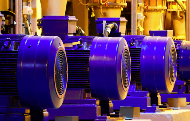
An electric motor is a piece of equipment that converts electrical energy into mechanical energy. It commonly consists of a rotor (the motor's moving component) and a stator (the motor's fixed component), as well as an armature and a field magnet.
Electric motors are used in a wide range of applications, from small domestic appliances to huge industrial machines, and can be powered by direct current (DC) or alternating current (AC). DC motors, AC motors, and stepper motors are all typical forms of electric motors. Electric motors are efficient and dependable, and they can be readily regulated and altered to meet a variety of purposes.
In this article, we will only cover the three-phase alternating current motors.
 |
| Hierarchical Tree of the Types of Electric Motors |
There are several types of electric motors, each with their own unique characteristics and best suited applications. From the diagram given above, electric motors are categorized with respect to the type of supply voltage where it will be connected. From there, all different type of motors used in the industry are classified further.
Alternating Current Motors
An alternating current (AC) motor is a type of electric motor that converts electrical energy from alternating current (AC) to mechanical energy. It is normally made up of a rotor (the motor's rotating component) and a stator (the stationary part of the motor). When connected to an alternating current power source, the stator generates a rotating magnetic field that causes the rotor to turn.
Induction Motor
An induction motor, also known as an asynchronous motor, is an alternating current motor in which the rotor rotates at a slightly slower speed than the revolving magnetic field of the stator. The stator causes the rotor to rotate by inducing an electromotive force. Induction motors are well-known for their ease of use, dependability, and efficiency. Fans, pumps, and conveyors are common industrial and commercial applications for these.
The main parts of a 3-phase induction motor include:
Stator - The stator is the stationary part of the motor that houses the windings that create the rotating magnetic field. It is typically made of laminated steel and is designed to provide a high level of efficiency and low levels of noise and vibration.
Rotor - The rotor is the moving part of the motor that rotates inside the stator. It is typically made of cast iron or aluminum and is designed to provide a high level of strength and durability.
Bearings - The bearings are used to support the rotor and allow it to rotate smoothly and efficiently. They are typically made of high-quality materials such as steel or ceramic and are designed to provide a long service life.
Enclosure- The enclosure is used to protect the motor from environmental factors such as dust, moisture, and vibration. It is typically made of steel or aluminum and is designed to provide a high level of protection while still allowing for easy access to the motor for maintenance and repair.
 |
| Induction Motor |
In terms of design and use, there are a few different kinds of induction motors, and the manner each one is used varies depending on the voltage level at which it is operated.
Here are some examples:
Low Voltage Induction Motors
A low voltage 3-phase induction motor is an electric motor that runs on a three-phase power supply with a voltage level of 380-480V. It is a type of asynchronous motor, which means that the rotor rotates at a slightly slower speed than the rotating magnetic field created by the stator windings. These motors are widely used in industrial and commercial applications such as pumps, fans, conveyors, and machine tools. They are known for their high starting torque, high efficiency, and low cost. They are also relatively easy to control and maintain, making them a popular choice for a wide range of applications.
There are several different methods that can be used to start a low voltage induction motor, including:
Direct-on-line (DOL) starting - This is the most basic method of starting an induction motor. It involves simply applying full voltage to the motor terminals. This method is simple and reliable, but it generates high inrush current and high mechanical stress, which can lead to damage to the motor or other equipment.
Star-delta starting - This method involves starting the motor in a star-connected configuration and then switching to a delta-connected configuration after the motor has reached a certain speed. This reduces the starting current and torque, but it is not as efficient as other methods.
Auto Transformer starting - This method uses an auto transformer to reduce the starting voltage applied to the motor. This reduces the starting current and torque, but it is not as efficient as other methods.
Soft starter - A soft starter is an electronic device that controls the voltage applied to the motor during starting, reducing the starting current and torque. It is more efficient than other methods, but it requires additional equipment and control.
Variable Frequency Drive (VFD) Starting - A VFD is an electronic device that controls the frequency and voltage applied to the motor during starting, reducing the starting current and torque. It also allows for speed control during operation. It is more efficient than other methods, but it requires additional equipment and control.
The choice of starting method will depend on the specific requirements of the application and the equipment being used. Some starting methods may be more suitable for certain applications than others.
Medium voltage Motors
A medium voltage 3-phase induction motor is an electric motor that runs on a three-phase power supply with a voltage level of 2.3kV to 13.8kV. It is a type of asynchronous motor, which means that the rotor rotates at a slightly slower speed than the rotating magnetic field created by the stator windings.
Accordingly, when it comes to its main parts, it is almost the same with the LV motors. The main difference between them is MV motors requires more stringent protection during operation. In terms of protection, medium voltage induction motors are typically protected by a combination of mechanical and electrical protection devices. These include:
Overload protection - This is designed to protect the motor against excessive current or thermal overload.
Short-circuit protection - This is designed to protect the motor against damage caused by short-circuiting of the stator or rotor windings.
Ground-fault protection - This is designed to protect the motor against damage caused by ground faults in the stator or rotor windings.
Unbalanced voltage protection - This is designed to protect the motor against damage caused by unbalanced voltage in the stator windings.
Under/over voltage protection - This is designed to protect the motor against damage caused by under or over voltage.
The complete set of Medium Voltage motor protection will be discussed in another article.
Synchronous Motor
A synchronous motor is an alternating current motor that operates at a rate that is synchronized with the line frequency. It has a rotor that revolves at the same rate as the revolving magnetic field of the stator. The rotor is usually a permanent magnet or a field winding that is powered by direct current. Synchronous motors have a high efficiency, a high-power factor, and a constant speed.
Synchronous motors are AC motors that run at a constant speed, determined by the frequency of the power supply and the number of pole pairs in the rotor. The speed of a synchronous motor is synchronous with the frequency of the power supply and is independent of the load on the motor.
 |
| Synchronous Motor showing the Separate DC Supply Connected to the Rotor |
The main difference between the two is that in Induction Motor the rotor runs at a slightly slower speed than the stator's rotating magnetic field and in Synchronous Motor the rotor runs at the same speed as the stator's rotating magnetic field because there is. Induction motors are typically simpler, less expensive, and more reliable than synchronous motors. Synchronous motors are typically more efficient but require more complex control systems.
The table below shows the main difference between the two types of motors.
|
Induction Motor
|
Synchronous Motor
|
|
Rotor runs at
a slightly slower speed than the stator's rotating magnetic field
|
Rotor runs at
the same speed as the stator's rotating magnetic field
|
|
Rotor is an
electromagnet
|
Rotor is a
permanent magnet or contains a field winding
|
|
Speed is
determined by the frequency of the power supply and the number of stator
poles
|
Speed is
determined by the power supply frequency and the number of rotor poles
|
|
Speed can vary
slightly due to load changes
|
Speed is
constant regardless of load changes
|
|
Simple
construction and control
|
More complex
construction and control
|
|
Lower cost
|
Higher cost
|
|
High efficiency
|
Higher
efficiency
|
|
typically have
lower starting torque
|
typically have
high starting torque
|
Use of Synchronous Motors
Constant speed drives - Synchronous motors are used in constant speed applications such as fans, pumps, and compressors, where a constant speed is required regardless of the load on the motor.
Power generation - In a gas power plant, the rotor of a synchronous generator can be used as a motor while the turbine is getting up to speed. This is done by supplying power from outside the plant to the rotor. Most of the time, this outside power source is a DC power supply, which is used to give the rotor a rotating field. As the speed of the turbine goes up, the generator's internal excitation goes up, letting it take over as the rotor's main source of power. Once the turbine is running at full speed, the generator switches from motoring to generating mode and starts making AC power.
Power factor correction - Synchronous motors can be used to correct power factor in an electrical system by absorbing or generating reactive power, as required.
Grid stabilization - Synchronous motors can be used to stabilize the power grid by providing a reference frequency to the grid and regulating the voltage.
Synchronous motors are typically more efficient and have a higher power factor than asynchronous motors, but they also have a higher initial cost and require more maintenance. They are also more complex to control and require special devices such as exciters to generate the necessary field current for the rotor to run.
It is important to note that the choice of motor depends on the specific application and the trade-offs between cost, efficiency, and performance.


.webp)


No comments: