What are the different types of Neutral Grounding Resistors?
 |
| Neutral Grounding Resistors |
A neutral grounding resistor is a resistor that is connected to a system's neutral grounding point. Its job is to limit the amount of fault current that flows through the neutral point. This protects equipment and makes electrical fires less likely. It is most often used in power plants and other large industrial facilities where there is a high chance of a fault current. Neutral grounding resistors do more than just limit fault current.
They also do other important things.
For example, they can help make a system more stable by giving harmonic currents a path with low resistance. They can also help cut down on the voltage spikes that can happen when something goes wrong and damage equipment or causes power interruption.
Related Article: Neutral Grounding of Industrial Power Systems
Neutral grounding resistors are usually made of a high-resistance material, like carbon or a metal alloy, and are made to have a very low thermal coefficient of resistance. This makes sure that their resistance stays the same over a wide range of operating temperatures and conditions. They are also rated for a certain amount of current and voltage. The current rating is the most important because it will help you figure out how big the resistor needs to be.
What are the different types of Neutral Grounding Resistors?
Neutral Grounding Resistor
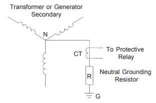
Neutral grounding resistors are rated in line-to-neutral voltage (system voltage divided by 1.732), initial fault current and maximum time on. These resistors are designed to dissipate the required amount of energy and not exceed the temperature limitations of IEEE Standard 32-1972.
 |
| Source: Powerohm Resistors, Inc. |
As defined in this publication, the time and temperature ratings for neutral grounding resistors are as follows:
- Short time: Short time ratings are 10 and 60 seconds. Since short time rated resistors can only withstand rated current for short periods of time, they are usually used with fault clearing relays. The short time temperature rise for the resistive element is 760°C.
- Extended time: A time on rating greater than ten minutes which permits temperature rise of resistive elements to become constant but limited to an average not more than 90 days per year. The extended temperature rise for the resistive element is 610°C.
- Continuous: Capable of withstanding rated current for an indefinite period of time. The continuous temperature rise for the resistive element is 385°C.
Related Reading: What is the Importance of Industrial Grounding?
Generator Neutral Grounding Resistor
This offers high resistance grounding equipment for wye connected generators. this equipment is normally designed to limit the line-to-ground fault current to below 15 amps for generators rated up to 14,400 volts.
 |
| Source: Powerohm Resistors, Inc. |
These units will provide a high resistance neutral during a fault condition, while allowing the system to operate as an ungrounded system during normal operating conditions. The configuration basically consists of a dry-type single-phase transformer with a resistor connected across the secondary. The primary of the transformer is then connected between the wye point of the generator and ground.

This equipment is normally supplied with the transformer and resistor installed in a common enclosure. Continuous rated units are usually compartmentalized to separate the resistor assembly from the transformer which is subject to overheating. Units do not normally include any relaying or control circuitry but do offer the transformer secondary wired to a terminal block installed in an external junction box.
Resistance Grounding with a Zigzag Transformer
 |
| Source: Powerohm Resistors, Inc. |


.webp)


No comments: