What is Current Transformer Knee Point?
What is Current Transformer?
Current transformers (CTs) are devices that are used to measure the current flowing in an electrical circuit. They work by producing a secondary current that is proportional to the primary current flowing through the CT's core. This secondary current can then be measured by a meter or other monitoring device, allowing for accurate measurement and monitoring of the electrical system.
Related Article: Instrument Transformers in Power System Protection
Uses of Current Transformers
Current transformers (CTs) are widely used in the electrical power industry for a variety of applications. Some of the main uses of CTs include:
- Measurement - CTs are primarily used for measuring electrical currents in high-voltage and high-current power systems. They are used to step down the current flowing through a power line to a level that can be accurately measured by a meter or monitoring device.
- Protection - CTs are also used for protection purposes, such as detecting overcurrent, undercurrent, or ground fault conditions in a power system. In these applications, the CTs are connected to protective relays that monitor the current flowing through the power system and trip circuit breakers or disconnect switches in case of a fault.
- Metering - CTs are commonly used for revenue metering in the utility industry, where accurate measurement of power consumption is essential for billing purposes. The CTs are used to measure the current flowing through the power lines, which is then used to calculate the power consumption.
- Monitoring - CTs are used for monitoring the performance and efficiency of electrical equipment, such as motors, generators, and transformers. The CTs can be used to measure the current flowing through the equipment, which can be used to diagnose any problems or issues that may arise.
- Power Quality Analysis - CTs are used for power quality analysis, which involves monitoring and analyzing various parameters of the electrical power system, such as voltage, current, and frequency. The CTs are used to measure the current flowing through the power system, which can be used to identify issues such as harmonics, voltage sags, and power factor problems.
The CT Knee Point
The knee point is the point at which the CT core begins to saturate due to the magnetic flux density becoming too high. As the core saturates, the output of the CT becomes non-linear, which means that the ratio of primary current to secondary current is no longer linear. This can result in inaccurate measurements and can lead to errors in the monitoring and protection of the electrical system.
 |
| Figure 1. CT Knee Point |
How to Determine CT Knee Point?
For example, if a CT has a knee point of 50A, it can accurately measure up to 50A, any primary current above 50A will cause the CT to operate non-linearly, leading to inaccurate measurements.
- Short Circuit Current
- CT secondary resistance
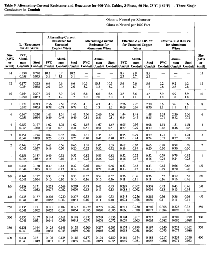
- The resistance of the wire that connects the CT and the relay.
- Burden of the relay


.webp)


Really informative breakdown of how CTs work and why the knee point matters! It’s great to see such technical concepts explained so clearly. As someone offering article writing services, I appreciate well-structured content like this that makes complex topics easy to understand.
ReplyDelete