What are the Conditions in Selecting Current Transformer in Protective Relaying
Current Transformer
The current transformer is one of the main essential components in protective relaying. Along with Potential Transformers (PT), this device is also the key element that will detect any abnormalities in the system. When it comes to protective relaying applications, the CT that will be used is those with large cores that allow the replication of the primary current during fault condition (high primary current).
However, we should not rely on the physical sizes of selecting the right unit to use. We need to satisfy the essential requirements to prevent undesirable results. In order to achieve this goal, we need to comply with two conditions, namely:
Condition 1: The current rating of the primary must be close to the full load current of the load or the system that it protects. For example, if the full load current is 387 Amperes, then it is better to choose a CT that has a conversion ratio of 400:5.
Condition 2: Calculate the secondary voltage at the time of the fault to determine whether the CT will saturate during a fault condition. In this case, even if we satisfy condition 1, we need to select the next higher rating and do the same process.
How to determine CT Saturation?
To determine whether a CT will saturate in a certain condition, we need to find the following values:
- Amount of fault current
- CT Secondary Resistance
- Wire resistance that connects CT and the protection relay
- The Burden resistance of the relay.
Example:
A protection relay is to be installed to a motor with full load current rating of 290. A CT with conversion ratio of 300:5 will be used and it has a total distance of 20 meters from the relay. The wire has a resistance of 1.5 ohms per kilometers. If the CT secondary resistance is 0.09 ohms and the relay burden resistance is 0.005 ohms. Determine if the CT ratio will saturate based on the curve given below.
Note: Assume that the fault current in the system is 3.5 kA.
Solution:
In this case, we will enumerate the given values as,
- CT to be used is 300 : 5
- Fault current = 3,500 Amperes
- CT secondary resistance = 0.090 ohms
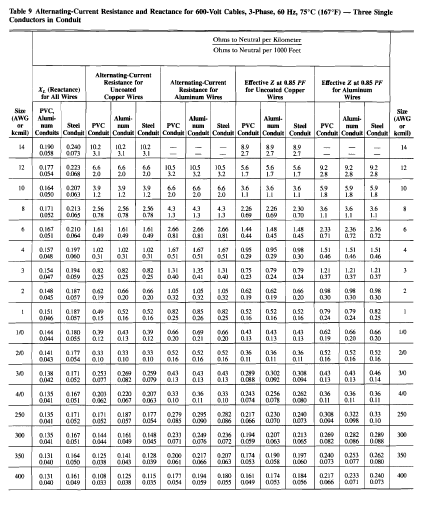
- Wire distance to relay = 20 mtrs rated @ 1.5 ohms/ km
- Relay burden resistance = 0.006 ohms
Calculate the wire resistance:
Rwire = (2 x 20 m) x 1.5 ohms/ km
1000
Rwire = 0.06 ohms
Calculate the total burden
Total Burden = RCT (secondary) + Rwire + R relay
Total Burden = 0.090 + 0.06 + 0.006 = 0.156 ohms
Calculate the Secondary Voltage in the event of fault.
V = (Total Burden * Fault Current)/ CT ratio
V = (0.156 * 3,500) / 60
V = 9.1 Volts
Check the CT Curve if the secondary voltage in the event of fault is below the KNEE POINT.
The value of secondary voltage in the event of a fault is 9.1 Volts which is below the knee point. Therefore, we can accept the 300:5 CT given in the problem. Otherwise, we will choose the next higher value and do the same process because the value of secondary current with respect to the primary value is no longer linear. Non-linearity of these values will result in the inaccuracy of readings and malfunction of protection relays that connects to it. This situation could result in catastrophic damage on the part of the whole power system.


.webp)


No comments: