Power Factor Correction and Harmonic Filtering
What is Power Factor?
Power factor is a crucial concept in electrical engineering that represents the efficiency of power transfer in an alternating current (AC) circuit. It is defined as the ratio of real power (P) to apparent power (S), which can be expressed mathematically as:
Power factor (PF) = Real Power (P) / Apparent Power (S)
Real power (P), measured in watts (W), represents the actual power consumed by the electrical load to perform useful work. Apparent power (S), measured in volt-amperes (VA), is the product of the voltage and current in the circuit. It comprises both real power and reactive power (Q). Reactive power, measured in volt-amperes reactive (VAR), is the power required to maintain the magnetic and electric fields in inductive and capacitive loads, such as transformers, motors, and capacitors. It does not contribute to the useful work but causes energy loss in the form of heat and noise.
Related Article: How to Understand Power Triangle In Three Phase AC System
The power factor ranges from 0 to 1, where a power factor of 1 (unity) indicates that all the power is being used efficiently, and a lower power factor means that more reactive power is present, reducing the efficiency of the system. Power factor can be leading (capacitive loads) or lagging (inductive loads).
What is Power Factor Correction?
Power factor correction (PFC) is the process of improving the power factor of an electrical system, which increases the efficiency of power transfer in alternating current. Power factor correction is necessary because many electrical loads, particularly those with inductive components (e.g., motors, transformers, and induction furnaces), introduce reactive power into the system. Reactive power does not contribute to useful work but circulates between the source and the load, causing energy losses in the form of heat and noise, and reducing the overall efficiency of the power system.
 |
| Figure 1. Power Triangle in Alternating Current System |
Every electrical system (cable, line, transformer, motor, lighting, etc.) employs two forms of energy:
- Active energy consumed (kWh) - This is fully transformed into mechanical, thermal or luminous power. It corresponds to the active power P (kW) of the loads.
- Reactive energy consumed (kvarh). - It serves to magnetize motors and transformers. It corresponds to the reactive power Q (kvar) of the loads. It results in a phase difference (ϕ) between the voltage and current. This is an energy that is “necessary” but produces no work.The reactive energy demanded by the loads is supplied by the electrical network. This energy must be supplied in addition to the active energy. This flow of reactive energy over the electrical networks results, due to a larger current demand, in: additional voltage drops, transformer overloading, and overheating in circuits... and hence losses.
The primary goal of power factor correction is to minimize reactive power and improve system efficiency. This can be achieved by adding capacitors or synchronous condensers, which provide leading reactive power, to the electrical system. These devices help balance the lagging reactive power caused by inductive loads, thus improving the overall power factor. (AC) circuits.
Related Article: Power Factor Correction in AC System
What is the Importance of Power Factor Correction?
Importance of power factor correction:
- Improved energy efficiency - Power factor correction minimizes reactive power and reduces energy losses, improving the overall efficiency of the power system.
- Reduced utility costs - Many utility companies charge commercial and industrial customers based on their power factor. A low power factor may result in higher electricity bills. By improving the power factor, you can reduce your energy costs.
- Increased load-carrying capacity - A low power factor reduces the capacity of the electrical system to carry useful power. By correcting the power factor, you can increase the load-carrying capacity of your electrical system without upgrading the infrastructure.
- Extended equipment life - By reducing the reactive power, power factor correction reduces the stress on electrical equipment, such as transformers, generators, and motors, extending their life and reducing maintenance costs.
 |
| Figure 2. Reduction in Transmission Losses | Source: Schneider Electric |
Power factor correction is typically achieved by installing capacitors or synchronous condensers in the electrical system. These devices provide leading reactive power, which compensates for the lagging reactive power caused by inductive loads, improving the overall power factor.
PF Correction Design Scheme for Different Application
Capacitor Banks for MV Motor Compensation
Power factor correction for motor compensation is primarily used to improve the efficiency and performance of an electrical system with the existence of large electric motors particularly in medium voltage system. Inductive loads, like motors, create reactive power that does not contribute to useful work but instead circulates between the source and the load, causing energy losses in the form of heat and noise. Reactive power also reduces the overall efficiency of the power system and leads to a lower power factor. This device can be applied for systems up to 12 kV.
 |
| Figure 3. Capacitor Bank for MV Motor Compensation | Source: Schneider Electric |
Capacitor Bank for Industrial Compensation
Instead of installing a capacitor bank for individual equipment compensation, a capacitor bank can be also installed as group of capacitors connected in parallel or series configuration, used for industrial compensation to improve the power factor. These units are commonly installed in industrial environments, where electrical loads often include inductive components, such as motors, transformers, and induction furnaces. These inductive loads generate reactive power, which leads to a lower power factor and reduced system efficiency.
Figure 3 shows banks that is delta-connected (three-phase capacitors) and the HRC fuses provide protection against internal faults. An optional cubicle containing a power factor controller can be used to control the steps, thus forming an automatic compensation bank. For steps power values greater than 900 kvar, single-phase capacitors connected in double star will be used (maximum of 12 capacitors, maximum power 4500 kvar).
 |
| Figure 4. Capacitor Bank for Industrial Compensation | Source: Schneider Electric |
Capacitor Banks for Distribution Networks.
In principle, this capacitor banks will serve similar purpose to what has been show above. However, the application of these units are intended for larger area such as in distribution networks. In distribution networks, a significant amount of inductive loads, such as motors, transformers, and other equipment, generates lagging reactive power. This reactive power leads to a lower power factor, causing inefficiencies in the system and increased costs for both utilities and end-users. Capacitor banks provide leading reactive power, which counteracts the lagging reactive power produced by inductive loads, resulting in an improved power factor.
 |
| Figure 5. Capacitor Bank for Distribution Network | Source: Schneider Electric |
Figure 4 shows capacitor banks that are connected in double star and the unbalance current detection system provides protection against internal faults. Several banks (in that case called “steps”) can be controlled by a power factor controller to form an automatic capacitor bank. The steps are connected in parallel with power cables (outside our scope of supply).
These units can be applied to voltages up to 36 kV.
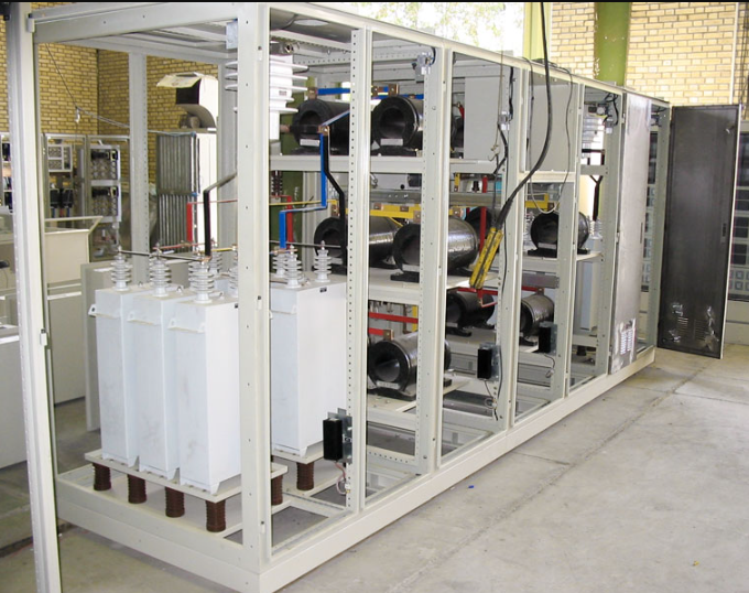
What is the Effect of Harmonics on Capacitors?
Harmonics are sinusoidal voltage and current waveforms with frequencies that are integer multiples of the fundamental frequency (usually 50 or 60 Hz). They are generated by non-linear loads, such as power electronic devices, variable frequency drives, and fluorescent lights.
Harmonics can have negative effects on electrical systems and components, including capacitors used for power factor correction.
Capacitors are sensitive to heating effect caused by harmonics. The impedance of a capacitor is inversely proportional to the frequency. As the frequency increases, the impedance decreases, meaning capacitors offer less resistance to harmonic currents. Therefore, higher order harmonic currents can flow more easily through capacitors than the fundamental frequency.
 |
| Figure 6. Passive Harmonic Filter |
When harmonic currents flow through a capacitor, they cause power losses due to the inherent resistance (Equivalent Series Resistance or ESR) and dielectric losses within the capacitor. The power loss (P_loss) can be calculated as P_loss = I² * R, where I is the current flowing through the capacitor and R is its equivalent series resistance. As the harmonic currents increase, the power loss in the capacitor also increases.
To mitigate the heating effects of harmonics in capacitors, it is crucial to identify and address the sources of harmonics in the system. Additionally, using harmonic filters, active harmonic compensators, or de-tuned capacitor banks can help reduce the impact of harmonics on capacitors and improve the overall performance and reliability of the electrical system.
Also, the solutions to limit stress due to harmonics can be achieved by the following methods:
- Oversizing of capacitor links to the network - cables, lines, switchgear and control gear should be sized for at least 1.43 Ic, the value of the capacitor’s rated current at 50 Hz;
- voltage oversizing of capacitors -
- use of detuning reactors combined with oversized capacitors.
In MV, the detuning reactor connected in series with the capacitor is generally designed to form a capacitor bank tuned to 215 Hz (50 Hz) or 260 Hz (60 Hz). Since this frequency corresponds to no harmonic order, it makes it possible to reduce both the harmonic overvoltages across the terminals of the capacitor as a result of the resonance, and the overload currents passing through the capacitor.
In conclusion, power factor correction and harmonic filtering are essential aspects of maintaining efficient, reliable, and stable electrical systems. By improving the power factor, power factor correction techniques help reduce energy losses, lower utility costs, increase load-carrying capacity, and enhance the overall performance of electrical networks.
However, the harmonic filtering cannot be implemented right away without considering the effect of harmonics to capacitors. In this case, harmonic filtering plays a vital role in mitigating the negative impacts of harmonics on electrical components and system performance. Together, power factor correction and harmonic filtering contribute to the optimal operation of electrical systems, ensuring energy efficiency, reduced operational costs, and extended equipment life for both utilities and end-users.
~ End
View or Download PDF
- Title: Power Factor Correction and harmonic filtering solutions
- Source: Schneider Electric


.webp)


commands WAEC QUESTION AND ANSWER furnished with the useful resource of WAEC QUESTION AND ANSWER WAEC. Right here's information approximately WAEC QUESTION AND ANSWER
ReplyDeleteGreat explanation of power factor and why correction is important—it really clears up the difference between real and reactive power. Reading it felt as smooth and straightforward as exploring the neat layout on labubukeychain.shop, where everything is presented with clarity and purpose.
ReplyDeletePower Factor Correction and Harmonic Filtering play a crucial role in improving electrical system efficiency by reducing energy losses and ensuring stable power quality. These technologies help industries lower electricity costs, minimize equipment wear, and maintain a cleaner, more reliable power supply. As businesses move toward smarter energy management, understanding these solutions becomes even more important. In a similar way, modern digitizing services help companies enhance accuracy and efficiency in their embroidery production. Both fields rely on precision, technology, and optimization—whether it's stabilizing electrical performance or converting artwork into flawless stitch-ready embroidery files.
ReplyDeleteRecomiendo https://www.jugabet.cl/services/lobby a quienes valoran una experiencia simple. El lobby permite entrar a distintos juegos desde un mismo lugar, sin perder tiempo navegando. Todo se siente ordenado, lo que hace más agradable cada sesión de juego, incluso si juegas solo unos minutos.
ReplyDelete