Design Considerations to Enhance Safety and Reliability for Service Entrance Switchboards
 |
| Switchboard |
Switchboards are a widely used type of equipment in low-voltage electrical distribution systems. They are typically used as the service entrance equipment for a variety of facility types. While consideration of safety and reliability must be given to all parts of an electrical distribution system design, the impact of choosing the correct design options to enhance safety and reliability is magnified at a service entrance.
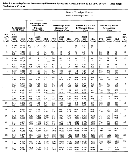
As an example, on a 480-volt service entrance fed by a 2,000- kilovolt-ampere (kVA) transformer with standard impedance, the low-voltage main breaker can limit incident energy to below 4 cal/cm2 when the low-voltage main breaker is allowed to clear arcing faults using its instantaneous response. The incident the energy on the low-voltage main breaker line-side would be over 130 cal/cm2 and have a corresponding arc flash boundary of 36 feet when the transformer primary is protected by a fuse1 . For non-compartmented switchboards, the highest incident energy calculated anywhere within the switchboard could be reflected on the arc flash labels for all sections in that continuous lineup. This can render the entire switchboard unapproachable while it is energized.
In the one-line below, a utility, or end-user-owned transformer is connected to a service entrance switchboard. The switchboard has a main breaker and any number of group or individually mounted feeder breakers. The overcurrent protective device (OCPD) that is upstream of the the transformer would typically be a fused switch or a medium-voltage breaker.
 |
| Typical Service Entrance | Source: General Electric |
The protection settings (in the case of the medium-voltage breaker), or fixed time-current characteristics (in the case of the medium-voltage fuse) determine how quickly an arcing fault will be cleared on the transformer secondary side down to the low-voltage main device terminals. For a given system, that upstream device clearing time will determine the arc flash energy on the line-side of the low-voltage main breaker.
Related Article: What are the different types of Circuit Breakers and It's Specific Uses
In a conventional switchboard service entrance design, the main breaker and the feeder breakers are connected by a hard bus such that the main section is in a continuous lineup with the feeder section(s). While this is convenient from the perspective of installation, it does have disadvantages when the arc flash energy at the line-side of the main breaker is greater than the load-side arc flash energy. High line-side arc flash energy can increase risks to workers interacting with other parts of the switchboard that is not part of the incoming section.
Options for Improving the Conventional Design
Options for Improving the Conventional Design
The concept is to provide distance between the higher arc flash energy normally found on the line-side of the low-voltage main device and the sections on the load-side. With sufficient distance between the main section and the feeder sections, the feeder breaker sections can be outside of the main section’s line-side arc flash boundary. This reduces the risk to personnel who interact with the feeder sections when the main breaker is appropriately set to clear arcing fault currents and allows workers within the arc the flash boundary of the feeder sections to wear personal protective equipment (PPE) appropriate for the incident energy at that location.
Maintenance Switching
A maintenance switch controls a temporary protection setting on a circuit breaker electronic trip unit and can provide benefits for any switchboard configuration. The temporary setting can be enabled to reduce the arc flash energy of an arcing fault on the low-voltage bus downstream of the breaker that has the maintenance switch function. A maintenance switch is typically enabled when an operator has to perform a task inside of the arc flash boundary. When the task is complete, the switch is set back to its default position which turns off the temporary protection setting.
Zone-Selective Interlocking
General
The safety benefit of a ZSI scheme is its potential to reduce arc flash energy on the system between the upstream and downstream breakers in the scheme. An arc flash study is needed to determine the appropriate protection settings to achieve the maximum benefit from the scheme. While maintenance switching is designed as a temporary arc flash energy reduction method (applied at specific times when operators interact with the equipment), ZSI is intended to be active continuously.
Short-Time ZSI
This can facilitate a lower arc flash energy for arcing faults on the switchboard bus compared to using coordinated short-time settings without ZSI. The amount of arc flash energy reduction possible is, in part, limited by the intentional time delay in the unrestrained short-time delay band. While the short-time ZSI can enhance protection without affecting the short-time coordination, it has no effect on any lack of selective coordination in the instantaneous range where overlap between main and feeder responses invariably occurs. Disabling the instantaneous response of the main breaker is not an option for switchboards that do not have a 30-cycle withstand rating.
Related Article: How to Interpret the Different Regions of Circuit Breaker Curves
Instantaneous ZSI
Instantaneous ZSI coordinates the instantaneous response of the breakers in the ZSI scheme. The upstream breaker in an instantaneous ZSI scheme uses its normal (unrestrained) instantaneous protection setting (without intentional delay) when there are no faults on the system or a fault occurs in the zone between the breakers in the ZSI scheme. The upstream breaker response moves from instantaneous to a fixed short-time delay band (restrained position) only if the downstream breaker senses a fault in the instantaneous range of pickup.
Summary
Each of the design options discussed can be considered as a discrete layer of improvement to the conventional switchboard design. The options can be applied individually or combined in various ways to best meet the needs of a particular situation. This white paper has elaborated on just a few of the design choices and equipment options that can be used to help enhance the safety and reliability of service entrance switchboards. Options such as draw-out mounting with remote racking, remote breaker operation, and remote monitoring should also be considered. While service entrance switchboards have been the focus of the white paper, the strategies discussed here can also be applied to non-service entrance switchboards to help improve safety and reliability.
Reference:
Title: Design Considerations to Enhance Safety and Reliability for Service Entrance Switchboards
Author: Robert P. Hansen, P.E,, Ph.D. (GE Specification Engineer)
Publisher: General Electric
Document Type: PDF | Download


.webp)


No comments: