Principles of Electric Motor Protection

Motors are used in a wide range of industries and applications, from manufacturing and construction to transportation and energy production. Here are some specific examples of motor applications accross industries:
- Fans, Blowers: Motors are used in fans and blowers in HVAC systems, as well as in industrial applications such as ventilation and air circulation. These motors must be efficient and able to operate at different speeds to adjust airflow as needed. HVAC experts, Millian Aire AC & Heating say that selecting the right motor type and size, along with implementing advanced control systems, is essential for achieving energy savings, maintaining indoor air quality, and ensuring optimal comfort levels in buildings.
- Pumps, Compressors: Motors are used in pumps and compressors for applications such as water treatment, oil and gas processing, and refrigeration. These motors must be able to provide high torque and operate continuously without overheating.
- Grinders, Chippers: Motors are used in grinders and chippers in the wood processing industry. These motors must be able to provide high torque and operate at different speeds to handle different materials and product sizes.
- Conveyors, Shredders: Motors are used in conveyors and shredders in material handling applications, such as in recycling facilities and food processing plants. These motors must be able to provide high torque and operate at different speeds to handle different materials and product sizes.
- Crushers, Mixers: Motors are used in crushers and mixers in the mining and construction industries, as well as in food and beverage processing. These motors must be able to operate at high speeds and provide high torque to handle tough materials and mixtures.
- Cranes, Extruders: Motors are used in cranes and extruders in various industries such as construction, manufacturing, and plastics processing. These motors must be able to provide precise positioning and control, as well as high torque and speed output.
- Refiners, Chillers: Motors are used in refiners and chillers in the chemical and pharmaceutical industries, as well as in food and beverage processing. These motors must be able to operate continuously and provide precise temperature control and cooling capacity.
These are just a few examples of the diverse range of motor applications in various industries. Motors are essential for many industrial processes and activities, and their performance and reliability are critical for efficient and safe operations.
Motor Failure Rates and Cost
Electric motors are crucial components in a wide range of applications, from industrial machinery to household appliances. However, like any mechanical or electrical system, electric motors can experience failure over time. The failure rate and causes of electric motors can vary depending on various factors such as the type of motor, operating conditions, and maintenance practices. Understanding the common causes of electric motor failure can help prevent unexpected downtime and costly repairs, while also improving the lifespan and performance of the motor.
- Motor failure rate is conservatively estimated as 3-5% per year. In Mining, Pulp and Paper industry, motor failure rate can be as high as 12%.
- Motor failures divided in 3 groups i.e. Electrical (33%), Mechanical (31%), Environmental, Maintenance, & Other (36%).
- Motor failure cost contributors i.e. Repair or Replacement, Removal and Installation, and Loss of Production.
 |
| Figure 1. Statistics of Motor Failure Rate |
Thermal Stress
Thermal stress is a significant cause of electric motor failure. When an electric motor is in operation, it generates heat due to the flow of electrical current and the friction of moving parts. Excessive heat can cause thermal stress, which can damage the motor's components and reduce its lifespan.
The effects of thermal stress on an electric motor can be numerous. For example, it can cause insulation breakdown, which can lead to short circuits, overheating, and ultimately motor failure. Thermal stress can also cause expansion and contraction of the motor's components, leading to misalignment, vibration, and bearing damage. Overheating due to thermal stress can also reduce the efficiency of the motor, increasing energy consumption and operating costs.
Preventing thermal stress is crucial to ensure the long-term performance and reliability of an electric motor. Proper ventilation, cooling systems, and regular maintenance can help manage heat buildup and reduce the risk of thermal stress-related failures.
Related Article: Control, Monitoring and Protection of High Voltage Motors
Stator Windings Insulation Degradation (for stator limited motors)
Overheating of an electric motor is a serious concern, as it can lead to various risks that can affect the motor's performance and reliability. First and foremost, an overheated motor can suffer significant damage to its insulation, which can result in short circuits and other electrical issues. This can not only damage the motor but also pose a safety risk to the equipment and people around it.
Another risk associated with overheating is the potential for mechanical failure. As the motor's components heat up, they can expand and contract, leading to misalignment, bearing damage, and increased vibration. These issues can cause additional stress on the motor, leading to premature failure, increased maintenance costs, and even safety hazards.
Insulation lifetime decreases by half if motor operating temperature exceeds thermal limit by 10ºC for any period of time.
 |
| Figure 2. Risk for an Overheated Motor |
Overheating can also have an impact on the motor's efficiency, leading to increased energy consumption and operating costs. As the motor works harder to overcome the additional heat generated, it can draw more power from the electrical supply, increasing energy bills and potentially causing power quality issues.
To prevent these risks, it is essential to monitor the temperature of the motor regularly and take appropriate steps to manage heat buildup. Proper ventilation, cooling systems, and regular maintenance can help mitigate the risks associated with an overheated motor, ensuring reliable and safe operation over the long term.
Motor Electrical Protections
Motor electrical protection is critical for ensuring the safe and reliable operation of electric motors. Electrical protection systems are designed to detect and respond to abnormal operating conditions, such as overloading, voltage spikes, and short circuits, which can damage the motor and cause safety hazards. There are various types of electrical protection systems available, including thermal overload protection, current protection, and voltage protection. These systems work by monitoring the motor's electrical parameters and triggering protective measures, such as tripping the motor or reducing the voltage, when abnormal conditions are detected.
Proper electrical protection is essential for preventing damage to the motor and extending its lifespan. Without adequate protection, an electric motor is at risk of suffering from insulation breakdown, overheating, and other issues that can lead to premature failure and safety hazards. To ensure the proper electrical protection of an electric motor, it is essential to choose the appropriate protection system for the motor's application, size, and operating conditions. Regular maintenance and inspection can also help identify potential issues and ensure that the protection systems are functioning correctly.
Related Article: Electric Motor Protection in Case of Voltage Unbalance and Single Phasing
Overload Protection - Thermal Model
The thermal overload protection system works by monitoring the temperature of the motor and triggering protective measures when the temperature exceeds a set threshold. The thermal model used in the protection system is based on the thermal time constant of the motor, which is a measure of how quickly the motor's temperature changes in response to changes in load and other operating conditions.
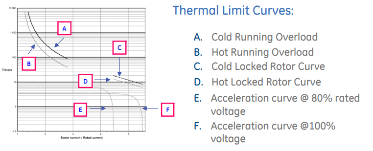 |
| Figure 3. Motor Thermal Limit Curves |
Motor thermal limit curves are graphical representations of the maximum temperature that an electric motor can withstand without suffering permanent damage. These curves provide a visual reference for determining the safe operating range of the motor and for selecting appropriate thermal overload protection systems.
The thermal limit curves are typically based on the motor's insulation class and its maximum allowable operating temperature. The curves illustrate the maximum permissible temperature for a given duration of operation, with longer durations corresponding to lower permissible temperatures.
Thermal Overload Pickup
Thermal overload pickup is a parameter used in thermal overload protection systems to set the threshold temperature at which the protection system will be triggered. The thermal overload pickup is typically set based on the motor's insulation class and maximum allowable operating temperature. The thermal overload pickup is used in conjunction with the thermal time constant of the motor to calculate the temperature rise of the motor for a given load and operating condition. When the calculated temperature rise exceeds the thermal overload pickup value, the thermal overload protection system is triggered, and the motor is disconnected from the power supply.
 |
| Figure 4. Sample Motor Nameplate |
- Set to the maximum allowed by the service factor of the motor.
- Set slightly above the motor service factor by 8-10% to account for measuring errors.
- If RTD Biasing of Thermal Model is used, thermal overload setting can be set higher.
- Note that motor feeder cables are normally sized at 1.25 times motor’s full load current rating, which would limit the motor overload pickup setting to a maximum of 125%.
Motor Over and Undervoltage Protection
 |
| Figure 5. Three phase voltage monitoring with phase sequence and phase failure relay |
Motor Unbalance Load Protection
Motor Ground Fault Protection
 |
| Figure 6. Motor having phase to ground fault. |
 |
| Figure 7. Differential Protection for motors |
Motor Short Circuit Protection
 |
| Figure 8. Circuit Breaker |
Stator RTD Protection
 |
| Figure 9. Temperature Sensors in a motor stator |
- Thermocouples - Thermocouples are temperature sensors that measure the voltage difference between two wires made of different metals. The voltage difference is proportional to the temperature difference between the two wires, which can be used to measure the temperature of the stator windings. Thermocouples are fast and accurate but have a limited temperature range and can be affected by electrical interference.
- Thermistors - Thermistors are temperature sensors that measure the resistance of a material, which varies with temperature. Thermistors can be used to measure the temperature of the stator windings and are less expensive than RTDs. However, they have a limited temperature range and can be affected by self-heating and aging.
- Infrared sensors - Infrared sensors measure the temperature of the stator windings by detecting the infrared radiation emitted by the motor. Infrared sensors are non-contact and can measure the temperature of the motor's surface. However, they are affected by the motor's surface properties and are not as accurate as other types of sensors.
View or Download PDF
- Title: Motor Protection Principles
- Source: General Electric

.webp)


Extremely useful information which you have shared here about Industrial Shredders This is a great way to enhance knowledge for us, and also beneficial for us. Thank you for sharing an article like this.
ReplyDeleteIf the battery will not be in use for a long time, it is suggested to be detached from the machine and placed in a cool, dry, clean place.Custom Lithium Battery Pack Manufacturer
ReplyDelete