𝗚𝗮𝘀-𝗜𝗻𝘀𝘂𝗹𝗮𝘁𝗲𝗱 𝗦𝘄𝗶𝘁𝗰𝗵𝗴𝗲𝗮𝗿 𝗠𝗼𝗱𝘂𝗹𝗲𝘀 (𝘂𝗽 𝘁𝗼 𝟰𝟮𝟬 𝗸𝗩, 𝟱𝟬 𝗸𝗔, 𝟱𝟬𝟬𝟬 𝗔)
 |
| Gas Insulated Switchgear | Source: Siemens Energy |
What is Gas Insulated Switchgear?
A Gas Insulated Switchgear (GIS) is a type of switchgear used in electrical power systems that uses a gas, such as sulfur hexafluoride (SF6), to insulate the high-voltage components of the switchgear.
The switchgear is typically used in high voltage substations, where the use of GIS has a number of advantages over traditional air-insulated switchgear. The main advantage is that GIS occupies much less space than air-insulated switchgear, making it possible to install high voltage equipment in densely populated urban areas. Additionally, GIS is highly reliable and requires minimal maintenance, and it is resistant to environmental factors like humidity and pollution.
GIS consists of a number of components, including circuit breakers, disconnectors, earthing switches, current transformers, and voltage transformers, all of which are contained within sealed metal enclosures filled with gas. When a fault occurs, the gas acts as an insulator, preventing an arc from forming and protecting the surrounding equipment from damage.
Related Article: What are the Important Characteristics of SF6 Circuit Breakers?
What is SF6?
SF6 (Sulfur hexafluoride) is a colorless, odorless, non-toxic, non-flammable gas that is widely used as an insulating gas in electrical power equipment such as circuit breakers, transformers, and gas-insulated switchgear (GIS). Despite its negative environmental impact, SF6 is still widely used in the electrical power industry due to its excellent insulating properties and its ability to conduct electricity. However, efforts are being made to find more environmentally friendly alternatives to SF6 for sustainable development.
How SF6 Extinguishes Arc?
When an electrical arc occurs in a gas-insulated switchgear (GIS) system, it produces high temperatures and ionizes the gas, causing a rapid increase in pressure. This pressure rise can cause significant damage to the surrounding equipment and pose a safety hazard.
Video 1: Electric Arc
SF6 gas is used in GIS systems as an insulator and also as a means of extinguishing electrical arcs. When an arc is initiated in the GIS, the SF6 gas is quickly heated by the energy of the arc and is ionized, creating a conductive path between the contacts of the circuit breaker. This conductive path allows the current to continue to flow even after the contacts have physically separated.
However, as the current flows through the ionized gas, the SF6 molecules are dissociated into their constituent atoms, creating a plasma of positively charged SF6 ions and free electrons. This plasma has a high electrical conductivity, which results in a rapid drop in the voltage across the arc. The reduced voltage, combined with the cooling effect of the expanding gas, extinguishes the arc in a matter of milliseconds.
Thus, SF6 gas is an effective means of extinguishing arcs in GIS systems due to its unique combination of properties, such as high insulating and arc-quenching capabilities, and high thermal conductivity.
Related Article: Case Study: Journey to SF6-free HV Substations
What are the Different GIS Modules?
Gas Insulated Switchgear (GIS) uses SF6 gas to insulate high voltage components. The circuit breaker is the main part of a GIS, housed in a sealed metal enclosure filled with SF6 gas, and capable of interrupting currents of several thousand amperes. Other components include disconnectors, earthing switches, current transformers, and voltage transformers, housed in sealed metal enclosures filled with SF6 gas. Despite the negative environmental impacts of SF6 gas, GIS is widely used in the electrical power industry due to its high reliability and efficiency. Efforts are underway to develop more environmentally-friendly alternatives.
Circuit Breaker
The central element of the gas-insulated switchgear is the circuit-breaker module with its two main com ponents:
- Interrupter unit and;
- Stored-energy spring mechanism.
For air-insulated switchgear (AIS) and gas-insulated switchgear (GIS), the same interrupter units and operating mechanism are used. The use of this plat form concept in a wide range of applications has pro vided us with decades of comprehensive experience. The circuit-breaker is suitable for single pole auto- reclosure.
 |
| Figure 1. Circuit Breaker with Interrupter Unit |
Related Article: What are the different type of circuit breakers and its uses?
Stored-energy spring mechanism.
State-of-the-art production techniques allow using compact housing. Since the closing and opening springs are housed in the operating mechanism, the structure is compact and sturdy. This design results in a small number of moving parts. The use of roller bearings and the mainte nance-free spring mechanism are a prerequisite for decades of reliable operation. Proven design princi ples, such as vibration-isolated latches and load-free isolation of the charging mechanism, are retained.The advantages of the stored-energy spring mechanism:
- One principle for rated voltages from 72.5 up to 550 kV.
- High reliability due to low operating energy.
- Simple principle of operation.
- Switching state controllable at all times.
- Low-maintenance, economical with a long service life.
- Low environmental impact.
 |
| Figure 2. Spring Mechanism |
Interrupter unit
Disconnecting Switches
Earthing Switches
- The three poles of a bay are coupled mechanically.
- All three poles are commonly operated by one motor mechanism.
- Auxiliary switches and ON/OFF indicators are friction locked.
- Identical motor operating mechanisms are used for disconnecting and earthing switches.
- Manual emergency operation is integrated.
- Enclosures can be fitted with inspection windows on request.
- High-speed earthing switches are single pole operated.
Instrument Transformers
- Current Transformer - The current transformers are of the single-phase inductive type and preferably located on the outgoing side of the circuit-breaker. They can, however, be located at any point within the bay or substation. The high-voltage conductor forms the primary winding. The cores with the secondary windings are designed for the specific project to comply with the requirements for accuracy, rating, etc. Different ratios can be achieved via taps in the secondary winding. Secondary connections are routed through a gas-tight bushing plate to a terminal box. The pressurized SF6 gas in the module serves as the primary insulation. The encapsulated design provides very high reliability in terms of electromagnetic compatibility (EMC).
- Voltage Transformer - Each single-phase inductive voltage trans former is encapsulated in its own housing, forming a separate gas-tight module. Each voltage transformer consists of the following main components: the primary winding; one or more secondary windings (forming one coil); and an iron core. The pressurized gas inside the enclosure together with the film insulation provides insulation against high voltage. The high-voltage connection to the switchgear is established by means of the primary conductor, which is supported by a gastight bushing. The secondary connections are routed via a gas-tight bushing plate to the terminal box.
Surge Arrester
Termination Modules
- Overhead lines
- Transformer or reactor
- Cables
Cable Termination
SF6/ Air Termination
Transformer tube-termination
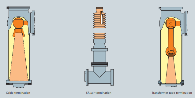 |
| Figure 3. Various Termination Module |


.webp)


No comments: