Busbar Protection
 |
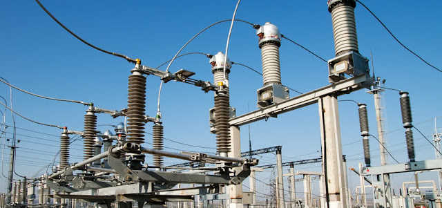
| Photo Credit: Schneider Electric |
The protection scheme for a power system should cover the whole system against all probable types of fault. Unrestricted forms of the line protection, such as overcurrent and distance systems, meet this requirement, although faults in the busbar zone are cleared only after some time delay. But if unit protection is applied to feeders and plants, the busbars are not inherently protected.
Related Article: Numerical Busbar Protection Scheme
Busbars have often been left without specific protection, for one or more of the following reasons:
- the busbars and switchgear have a high degree of reliability, to the point of being regarded as intrinsically safe
- it was feared that accidental operation of busbar protection might cause widespread dislocation of the power system, which, if not quickly cleared, would cause more loss than would the very infrequent actual bus faults
- it was hoped that system protection or back-up protection would provide sufficient bus protection if needed.
Busbar Protection Requirements
- Speed
- Stability
Speed
The busbar protection is primarily concerned with the limitation of consequential damage and the removal of busbar faults in less time than could be
achieved by back-up line protection, with the
object of maintaining system stability.
Some early busbar protection schemes used a low impedance differential system having a relatively long operation time, of up to 0.5 seconds. The basis of most modern schemes is a differential system using either low impedance biased or high impedance unbiased relays capable of operating in a time of the order of one cycle at a very moderate multiple of fault setting.
To this must
be added the operating time of the tripping relays, but an
overall tripping time of less than two cycles can be
achieved. With high-speed circuit breakers, complete
fault clearance may be obtained in approximately 0.1
seconds. When a frame-earth system is used, the
operating speed is comparable.
Stability
The stability of bus protection is of paramount
importance. Bearing in mind the low rate of fault incidence, amounting to no more than an average of one
fault per busbar in twenty years, it is clear that unless
the stability of the protection is absolute, the degree of
disturbance to which the power system is likely to be
subjected may be increased by the installation of bus
protection.
The possibility of incorrect operation has, in
the past, led to hesitation in applying bus protection and
has also resulted in application of some very complex
systems. Increased understanding of the response of
differential systems to transient currents enables such
systems to be applied with confidence in their
fundamental stability.
Type of Protection System
- system protection used to cover busbars
- frame-earth protection
- differential protection
- phase comparison protection
- directional blocking protection
Frame Earth Protection Scheme
Frame leakage protection has been extensively used in
the past in many different situations. There are several
variations of frame leakage schemes available, providing
busbar protection schemes with different capabilities.
The following section schemes have thus been retained
for historical and general reference purposes. A considerable number of schemes are still in service and
frame leakage may provide an acceptable solution in
particular circumstances. However, the need to insulate
the switchboard frame and provide cable gland
insulation and the availability of alternative schemes
using numerical relays have contributed to a decline in the use of frame leakage systems.
Single Busbar Frame to Earth Protection
This is purely an earth fault system and, in principle,
involves simply measuring the fault current flowing from
the switchgear frame to earth. A current transformer is
mounted on the earthing conductor and is used to energize
a simple instantaneous relay.
 |
| Single zone frame-earth protection |
Frame- Earth Protection- Sectioned Busbars
When the
busbar is divided into sections, these can be protected
separately, provided the frame is also sub-divided, the
sections mutually insulated, and each provided with a
separate earth conductor, current transformer and relay.
 |
| Frame-earth scheme: bus section breaker insulated on one side only |
Frame-Earth Scheme - Double Bus Substation
It is not generally feasible to separately insulate the
metal enclosures of the main and auxiliary busbars.
Protection is therefore generally provided as for single
bus installations, but with the additional feature that
circuits connected to the auxiliary bus are tripped for all
faults.
 |
| Frame-earth scheme for double busbar substation |
Frame-Earth Protection - Check System
On all but the smallest equipment, a check system
should be provided to guard against such contingencies. Faults in the low voltage auxiliary wiring must also be prevented from causing operation by passing current to earth through the switchgear frame. A useful check is provided by a relay energized by the system's neutral current or residual current.
If the neutral check cannot be provided, the frame-earth relays should have a short time delay. When a check system is used, instantaneous relays can be used, with a setting of 30% of the minimum earth fault current and an operating time at five times setting of 15 milliseconds or less.
 |
| Typical tripping and alarm circuits for a frame-leakage scheme |
Differential Protection Principles
The Merz-Price principle is applicable to a multi-terminal
zone such as a busbar. The principle is a direct
application of Kirchhoff's first law. Usually, the
circulating current arrangement is used, in which the
current transformers and interconnections form an
analogue of the busbar and circuit connections. A relay
connected across the CT bus wires represents a fault
path in the primary system in the analogue and hence is
not energised until a fault occurs on the busbar; it then
receives an input that, in principle at least, represents
the fault current.
Related Article: Fundamental of Generator Protection
Differential Protection
for Sectionalised and Duplicate Busbars
Each section of a divided bus is provided with a separate
circulating current system. The zones so formed are
over-lapped across the section switches, so that a fault
on the latter will trip the two adjacent zones.
 |
| Zones of protection for double bus station |
For double bus installation, the two busbars will be
treated as separate zones. The auxiliary busbar zone will
overlap the appropriate main busbar zone at the bus
coupler.
Since any circuit may be transferred from one busbar to
the other by isolator switches, these and the associated
tripping circuit must also be switched to the appropriate zone by 'early make' and 'late break' auxiliary contacts.
Reference:
- Network Protection and Automation Guide | Download

.webp)


No comments: