What are the Basic Characteristics of an Ideal Transformer?
 |
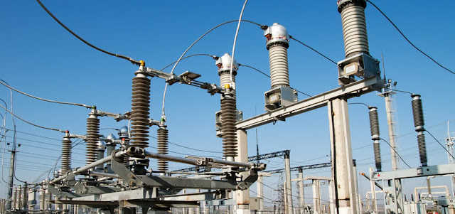
| Substation Transformer |
A transformer is an electrical piece of equipment that transforms the AC electrical power from one circuit to another. It makes use of the magnetically coupled coils to transfer energy.
Basically, it consists of a primary winding and secondary winding. The primary winding and its circuit are called the Primary Side of the transformer. The secondary winding and its circuit are called the Secondary Side of the transformer. Both the primary and the secondary winding of a transformer are electrically isolated from each other, but they are linked through the magnetic field.
Read:
Therefore, the primary and the secondary windings are magnetically coupled to each other. If the primary is connected to an alternating voltage source, an alternating flux is produced. The mutual flux will link the other winding (the secondary) to the primary and will induce a voltage in it. If the secondary winding is open (not connected to a load), the current in the primary winding is determined by its inductive.
The Ideal Transformer
An ideal transformer is a perfect transformer in which there is no power loss. In an ideal transformer:
- The windings are purely inductive with no resistance. Therefore, there are no copper losses in the windings.
- The iron core would not heat up during operation. Therefore, there are no losses in the iron core.
- The magnetizing current is zero, the current flow in the primary winding is zero when the secondary winding is open circuit.
 |
| Ideal Transformer |
Transformer Turns Ratio in an Ideal Transformer
- The magnetic flux is the same through the primary and the secondary windings.
- Therefore, the induced voltage per turn is the same in both the primary and the secondary.
- That means, Ep and Es are proportional to NP and NS respectively.
 |
| The Basic formula of an Ideal Transformer |
- If VP > VS the voltage is stepped down from a higher voltage to a lower voltage the transformer is then called a step-down transformer.
- If VP < VS, the voltage is stepped up from a lower voltage to a higher voltage, and the transformer is then called a step-up transformer.
- By interchanging the connections of the primary and the secondary windings, a step-down transformer can be made a step-up transformer.
Example:
In the figure shown below, determine the following:
a. the secondary voltage
b. the secondary current
c. the primary current
d. the power in the load
Solution:
a. From the given formula, we can say Vp/Vs = 3/1. Thus Vs = 20.
b. By ohms law, I = Vs/ R = 20/200; Is = 100 mA
c. From the formula, Vp/Vs = Is/Ip; Ip = Vp/Vs x Is = 1/3 x 100 mA; Is = 33.3 mA
d. Power flow in the load = Vs x Is = 20 x 100 mA; Pload = 2 Watts.


.webp)


In the "Ideal Transformer" drawing above, I believe you have drawn the current direction of the secondary opposite what it should be.
ReplyDelete