What are the Different Electric Current Symbols According to IEC Standard
IEC Standard provides nomenclature of currents in order for the designers to have a uniform approach to the design and installation. One of the most important consideration is the calculation of electric current because the proper sizes of cable and protection devices emanate from it. The size of cable and its protection equipment must satisfy several conditions in order to have a safe and reliable design and installation.
In this regard, IEC 60364 provides the following:
- Ib = Design Current
- Iz = Continous current rating of cable as provided by cable manufacturers that follows IEC standard.
- In = Nominal current rating of protection devices and in case the circuit breaker is adjustable, In refers to the selected value.
- Ia = The value of current that will cause the disconnection of the protective device at given time.
- I2 = The current rating ensuring the effective operation of the protective device which is also provided by the manufacturer manuals.
As a matter of safe design practices, IEC provides a useful relationship in order to guide electrical engineers in their design.
- Ib < = In < = Iz and I2 < = 1.45 x Iz
Example:
10 kW motor load connected to a 380 V AC supply with a pf of 0.8.
Find the design current Ib
Ib = 10,000 / (1.73 x 380 x 0.8) --> ignoring efficiency since the rating is already in kW
Ib = 19 Amperes
Find the circuit breaker rating In
Ib < = In or In > = Ib
For this situation, we can select a 20 Amperes MCB type C, 3 poles. Note that 19 < 25.
Note: Type C MCB, BSEN 60898 trips between 5 to 10 times of the rated value (Ia = 5 to 10 x In). So in case the motor is started using DOL starting, still, this breaker can withstand the inrush current.
Find the cable current rating Iz
In < = Iz or Iz > = In
IEC standard is open a possibility that IEC breakers could be installed together with non-IEC cables such as NEC standard cables. Thus, in critical installations, it is recommended to perform coordination studies between cable and protective devices.
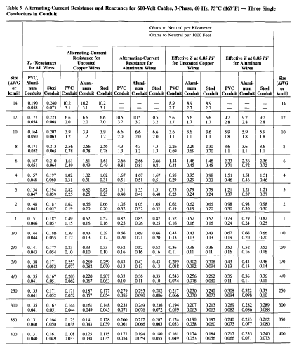
After getting the value of Iz, refer to cable manufacturer manual that follows IEC in order to find the right cable size to be used.
From the table given above, we need 6 sqmm cable (34 Amperes) to be used for the installation. Note that in this example, we neglect to consider the type of installation. We presume that the installation falls under Type A1 installation where there are two cables in a pipe which is installed within an insulated wall.
Multiple of Rated Current
Below is a typical IEC circuit breaker curve for MCBs with a thermal magnetic characteristic. Note that the lower limit of the curve started at 1.0 MRC while the upper limit started at 1.45 MRC.
MRC means Multiple of Rated Current. For example, the nominal rating of a circuit breaker In is 100 Ampere, then 1.45 MRC is 100 x 1.45 which is equal to 145 Ampere. This is to accommodate large values of current ratings.
So, what does it mean? Having a proper coordination of CB and cable means the cable damage curve must always be to the right side of the CB curve in order to protect the cable in case of fault and overload.
Note that this is a basic design process and in this example, the author did not incorporate voltage drop analysis and earth fault loop impedance which is also part of electrical design process.


.webp)


