The General Principles of Busbar Protection in Transmission and Sub-transmission Systems
 |
| High Voltage Busbar |
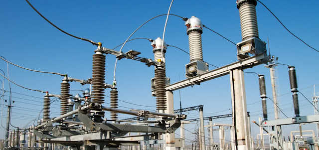
Busbar protection is a critical aspect of power system protection that involves detecting and isolating faults in the busbar section of a power substation. Busbar protection is critical for the safe and reliable operation of a power system.
Related Article: Busbar Protection
Like any other faults in the power system, busbar faults can cause significant damage to the power system equipment, including transformers, circuit breakers, and other components. However, busbar protection detects and isolates faults quickly, preventing damage to the equipment. In addition to preventing equipment damage, busbar protection also minimizes outage time by detecting and isolating faults quickly, allowing power to be restored to unaffected areas of the system. For this reason, the proper protection improves the reliability of the power system by minimizing the risk of cascading failures.
A fault on the busbar can cause a domino effect, leading to the failure of other components and causing a widespread outage. Proper protection prevents these cascading failures by detecting and isolating faults quickly. By isolating faulty components, maintenance crews can work safely on the equipment without the risk of electrical hazards.
Busbar Protection Design and Commissioning
- Identify the busbar arrangement - The first step in busbar protection is to identify the type of busbar arrangement. There are three main types of busbar arrangements: single busbar, double busbar, and ring busbar. Each arrangement has its own unique protection requirements.
- Select the protection scheme - Once you have identified the busbar arrangement, the next step is to select the appropriate protection scheme. There are several protection schemes that can be used for busbar protection, including differential protection, overcurrent protection, and distance protection.
- Install the protection relays - After selecting the protection scheme, you need to install the protection relays. The protection relays are the devices that detect and isolate faults in the busbar. The type and number of relays required will depend on the selected protection scheme.
- Set the protection parameters - Once the protection relays are installed, you need to set the protection parameters. The parameters include the pickup current, time delay, and other settings that determine when the protection relays will trip and isolate the fault.
- Test the protection system - After the protection relays are installed and configured, you need to test the protection system to ensure that it is working correctly. This involves performing primary and secondary injection tests, as well as testing the system under fault conditions.
- Commission the protection system - Once the protection system has been tested and verified, it can be commissioned. This involves integrating the protection system into the overall power system and ensuring that it is functioning correctly in normal operating conditions.
- Maintain the protection system - Busbar protection systems require regular maintenance to ensure that they continue to function correctly. This includes periodic testing and calibration of the protection relays, as well as inspection and maintenance of the associated equipment.
 |
| Typical Busbar and Connectors in a Substation |
Busbar Arrangement
Single Busbar - In a single busbar arrangement, all incoming and outgoing circuits are connected to a single busbar. This arrangement is simple and economical, but lacks redundancy, and a fault on the busbar can cause a complete outage of the substation.
 |
| Single Busbar |
Typical Double Breaker - In a typical double breaker arrangement, there are two independent busbars, each with its own set of incoming and outgoing circuits. This arrangement provides redundancy, so that if a fault occurs on one busbar, the other busbar can still supply power to the loads. Each busbar has two breakers, one as the main breaker and the other as the spare breaker, providing a backup in case of a breaker failure.
 |
| Typical Double Breaker |
Typical Breaker and Half - In a typical breaker and a half arrangement, there is one main busbar and one transfer busbar, each with one and a half circuit breakers. This arrangement provides redundancy and allows for more flexibility in the operation of the substation. The transfer busbar is usually smaller than the main busbar and is used as a backup in case the main busbar fails.
 |
| Typical Breaker and Half |
Double Busbar with Coupler- In a double busbar with coupler arrangement, there are two independent busbars, each with its own set of incoming and outgoing circuits, connected by a bus coupler. This arrangement provides redundancy and allows for more flexibility in the operation of the substation. The bus coupler allows power to be transferred between the two busbars, providing additional flexibility and redundancy.
 |
| Double Busbar with Coupler |
Related Article: Numerical Busbar Protection Scheme
Double Busbar and Transfer - In a double busbar and transfer arrangement, there are two independent busbars, each with its own set of incoming and outgoing circuits, and a transfer busbar that is used to transfer power between the two busbars. This arrangement provides redundancy and allows for more flexibility in the operation of the substation. The transfer busbar is usually smaller than the main busbars and is used as a backup in case one of the main busbars fails.
 |
| Double Busbar and Transfer |
Segregated Busbar with Transfer - In a segregated busbar with transfer arrangement, there are two independent busbars, each with its own set of incoming and outgoing circuits, and a transfer busbar that is used to transfer power between the two busbars. This arrangement provides redundancy and allows for more flexibility in the operation of the substation. The main busbars are segregated, meaning that they are physically separated from each other, providing additional safety and protection in case of a fault.
 |
| Segregated Busbar and Transfer |
Protection Requirements
Aside from the size of and busbar arrangements, there are several factors can affect the protection of busbars such as the fault current level, the time required to clear a fault, the type of fault, and the sensitivity of the protection relays.
The basic protection requirement of busbars includes the following:
- Differential protection - Differential protection is the most common principle used for busbar protection. The differential protection scheme compares the current flowing into and out of the busbar to detect a fault. If there is a fault, the differential current will be higher than the set threshold, and the protection relay will trip to isolate the fault.
- Overcurrent protection - Overcurrent protection is used as a backup protection for busbars. The overcurrent protection scheme uses current transformers to measure the current in the busbar. If the current exceeds a set threshold, the protection relay will trip to isolate the fault.
- Distance protection - Distance protection is used for large busbars and long transmission lines. The distance protection scheme measures the voltage and current at the point where the fault occurs and calculates the distance to the fault. If the calculated distance is within the set range, the protection relay will trip to isolate the fault.
- Voltage protection - Voltage protection is used to protect busbars from overvoltage and undervoltage conditions. The voltage protection scheme measures the busbar voltage and trips the protection relay if the voltage exceeds the set thresholds.
- Interlocking - Interlocking is used to prevent unwanted tripping of the busbar protection relays. The interlocking scheme ensures that the protection system is coordinated with other protection devices and prevents unwanted tripping. This includes settings such as the relay pickup and dropout times, and the use of blocking and tripping signals.
- Redundancy - Redundancy is used to ensure the reliability of the busbar protection system. A redundant protection scheme is used in which multiple protection relays are used, and each relay is set to trip at a different threshold. If one relay fails, the other relays will continue to provide protection.
Download or View PDF
- Title: Busbar Protection: General Principle and Application Examples
- Source: ALSTOM

.webp)


The General Principles of Busbar Protection in Transmission and Sub-transmission Systems outlines the key principles and techniques used to protect busbars in electrical power systems. It covers topics such as fault detection, relay selection, and protection coordination to ensure safe and reliable power transmission. The News Titan
ReplyDelete