Variable Frequency Drive and the Affinity Law
What is Variable Frequency Drive?
A variable frequency drive (VFD), also known as an adjustable frequency drive or variable speed drive, is an electronic device that controls the speed and torque of an electric motor by varying the frequency and voltage of the power supplied to it.
The VFD works by converting the fixed frequency AC power supply to DC power and then using an inverter to convert the DC power back into AC power at variable frequencies and voltages. This allows the VFD to precisely control the speed of the motor, which can result in significant energy savings and improved process control in many applications.
VFDs are used in a wide range of industries, including HVAC, water and wastewater treatment, manufacturing, mining, and many others. They are commonly used to control the speed of pumps, fans, and other motor-driven equipment, as well as to improve the efficiency and performance of industrial processes.
What is Affinity Law?
The affinity laws of centrifugal loads are a set of mathematical relationships that describe how changes in the speed, flow rate, or head of a centrifugal pump or fan affect its performance. These laws are important for engineers and technicians who work with centrifugal loads, as they can help predict how changes in operating conditions will affect the performance and efficiency of these devices.
The three affinity laws are as follows:
- The law of proportionality - The flow rate of a centrifugal pump or fan is directly proportional to the speed of the device.
- The law of similarity - When the speed of a centrifugal pump or fan is changed, the pump or fan will produce the same head at any particular flow rate, as long as the shape of the impeller and the fluid being pumped remain the same.
- The law of affinity - The power required to operate a centrifugal pump or fan is proportional to the cube of the speed of the device.
These laws can be used to predict the performance of centrifugal pumps and fans under different operating conditions and can be useful in optimizing their efficiency and reducing energy consumption.
Affinity Law Formula
Affinity laws are applied in centrifugal loads such as pump, compressor, fan, hydraulic system and the like. Affinity law comes in many form as a manifestation of interactions between power, flow rate, shaft speed, frequency and pressure head in centrifugal loads. Among the formulas within the Affinity Law is simple equation that states that the electrical power of any centrifugal load is directly proportional the shaft speed of the motor that drives it.
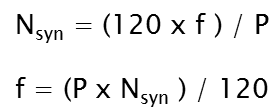
In electrical engineering we know from the formula of an induction motor that synchronous speed is also directly proportional to the frequency of the supply line.
Since speed is directly proportional to frequency (while taking the number of poles of the motor remains constant) we can say that any changes in the frequency has a corresponding linear changes in the synchronous speed of the motor.
For example a 4-pole motor is supplied with 440 volts AC, 60 Hz the synchronous speed for that is N= 120f / P is 1800 rpm (revolution per minute).
If we take the above example that a 4-pole motor has a synchronous speed of 1800 rpm at 60 Hz, we can reduced its synchronous speed into 900 rpm if we reduce the frequency to 30 Hz. And the device that can reduce that frequency is the Variable Frequency Drive. The reduction of the frequency can be attained by operating it manually or automatically.
From the given equations we can directly say that an 80% reduction of speed could result into 50% reduction of power consumption.
Application in the industry
Without so much dissecting it's theoretical background lets get straight on how can we be benefited on the application of the same. This can benefit us by using the VFD or the Variable Frequency Drive. VFD is a motor control device mainly used for speed control eliminating the use of gear box, belt, damper, and throttle if the full speed of the motor is not needed.A blower is inducing hot air to the bin in order to dry the grain products. This motor is designed for the maximum capacity of the drying bin. Sometimes the production volume cannot reach the maximum capacity or cannot even the reach the half of its capacity. In this case careful operator attention shall be done so as to prevent the product from being over dried or burning.
To overcome this problem, they installed valve at the side of the bin that would evacuate the excess hot air whenever necessary. This excess hot air manifests a waste of energy.
The solution is the installation of VFD. (see above schematic diagram)
In this case the Resistance Temperature Detector (RTD) (a kind of temperature sensor) is added to the system and its function is to detect temperature level and send the detected value to the temperature controller as an electrical signal.
The temperature controller now evaluates the received information and transmit analogue signal to the VFD (0-10 volts or 4-20 mA). The amount of current or voltage to be sent by the controller depends on the set value, set by the engineers or the operator.
The analogue signal will then be received by the VFD and serves as the determining factor on how much speed will the motor run.
In this method energy is saved!
The scenario is just one of the several examples wherein the VFD is installed to attain energy saving. In many industrial applications such as in compressors, air blast freezer and pumps application of VFD is necessarily important as far as savings is concern.
Guides in VFD selection
In selecting VFD's you have to properly consult the manufacturer or its authorized representative on what type of VFD is suited for your requirements. From different manufacturers there are different types and models of VFD.We will not choose VFD by considering the required power and voltage only but we have to consider also the environment that the VFD is to be installed whether it is exposed to dust, damp areas, humidity and other factors that if overlooked could affect the performance of the unit.
~ End


.webp)


No comments: