IEEE Guide for Protective Relay Applications to Power Transformers: Electrical Detection of Faults
 |
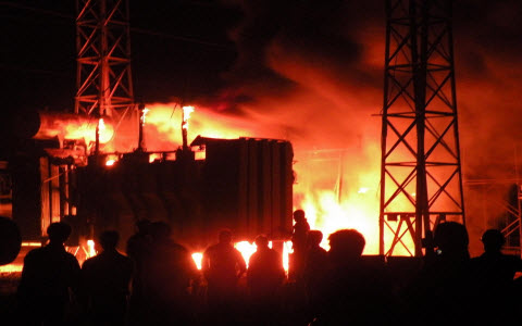
| Fire caused by unmitigated electrical fault |
Fuses are commonly used to provide fault detection for transformers with minimum nameplate ratings up to 5000 kVA, three-phase (Categories I and II).
Transformers of 10 000 kVA and larger, three-phase, minimum nameplates (Categories III and IV) are generally protected by a combination of protective devices.
Transformers that fall between these two ratings are protected by either fuses or relays. The choice of protection depends on the criticality of the load, the relative size of the transformer compared to the total system load, and potential safety concerns.
System considerations, such as coordinating fuses with upstream relays or with transformer damage curves, may determine what protection is used. Some other considerations include types of faults, personal safety issues, speed of clearing, single phasing of load, and ferroresonance.
Fuse protection
Fuses have the merits of being economical and requiring little maintenance. Battery supply and a relay building are not needed. Fuses can reliably protect some power transformers against damage from primary and secondary external faults. They will provide limited protection for internal faults. Generally, more sensitive means for protection from internal faults is provided for transformers of 10 MVA and higher. Fuses have been used at higher transformer ratings, depending on the currently available fuse ampere ratings. Primary fuses for power transformers are not applied for overload protection, their main purpose being fault protection.
The selection of the fuse and proper ampere rating should be based on the following factors:
- Fuse fault-interrupting capability and available system fault current.
- Maximum anticipated peak load current, daily peak loads, emergency peak loads, maximum permissible transformer load current, and the applicable transformer through-fault current duration curve.
- Fuse fault-interrupting capability and available system fault current.
- Maximum anticipated peak load current, daily peak loads, emergency peak loads, maximum permissible transformer load current, and the applicable transformer through-fault current duration curve.
- Hot load pickup (inrush current on instantaneous reclosing of source-side circuit breaker) and cold load pickup (inrush current and undiversified load current after an extended outage).
- Available primary system fault current and transformer impedance.
- Coordination with source-side protection equipment.
- Coordination with low-side protection equipment.
- Maximum allowable fault time on the low-side bus conductors.
- Transformer connections and grounding impedance as they affect the primary current for various types of secondary faults.
- Sensitivity for high-impedance faults.
- Transformer magnetizing inrush
Differential Protection
Current differential relaying is the most commonly used type of protection for transformers of approximately 10 MVA three-phase (self-cooled rating) and above. The term refers to the connection of CTs so that the net operating current to the relay is the difference between input and output currents to the zone of protection. Relays of three general classes are used with this current differential.
They are:
- Time overcurrent relay, which may include an instantaneous trip unit having a high-current setting.
- Percentage differential with restraint actuated by the input and output currents.
- Percentage differential relay, with restraint actuated by one or more harmonics in addition to the restraint actuated by the input and output currents.
 |
| Typical schematic connections for percentage differential protection
of a ∆-Y transformer Source: IEEE Guide for Protective Relay |
Overcurrent Relay Protection
A fault external to a transformer can result in damage to the transformer. If the fault is not cleared promptly, the resulting overload on the transformer can cause severe overheating and failure. Overcurrent relays may be used to clear the transformer from the faulted bus or line before the transformer is damaged. On some small transformers, overcurrent relays may also protect for internal transformer faults, and on larger transformers, overcurrent relays may be used to provide relay backup for differential or pressure relays. Thermal relays may also be used to protect transformers from harmful overload. However, thermal relays often are used for alarm only.
Overcurrent relay protection schemes for transformers:
- Phase time overcurrent
- Phase instantaneous overcurrent
- Tertiary-winding overcurrent.
Groud Fault Protection
Sensitive detection of ground faults can be obtained by differential relays or by overcurrent relays specifically applied for that purpose. Several schemes are practical, depending on transformer connections, availability of CTs, zero sequence current source, and system design and operating practices.
Gound fault protection schemes for transformers:
- Faults in DELTA connected transformer windings.
- Faults in WYE connected transformer windings.
- Case grounding
- Impedance grounded system
- Ground relays also used for sensitive ground fault protection.
Fault Detection for Special Purpose Transformers
 |
| Protection of grounding transformers: zigzag |

.webp)


thanks for this cool article <a href="https://www.bestprofessionalchainsaw.com/455-rancher-saw-cover/></a>
ReplyDeleteTo completely comprehend about lithium battery security, you should have an essential information on the volts at which they work.
ReplyDeleteBest Lithium Ion Battery Supplier
I recently found many useful information in your website especially this blog page. Among the lots of comments on your articles. Thanks for sharing.
ReplyDeletebar stools with backs
I have to say that when I clicked on this blog page, I wasn't expecting to discover such a wealth of information. It's like finding a hidden jewel in the long electronic world.
ReplyDeleteYou can also visit Skin Care Products to explore best range of skincare.
Oh wow I came here from a random link from another website. This is so informative content. There are many things to learn. I really appreciate your efforts. All concepts are so brief. So plz keep sharing such a well explained concept.
ReplyDeleteArmed Security Guard In Los Angeles County