Medium Voltage Technical Guide: Short Circuit Currents
 |
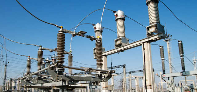
| Medium Voltage Switchgear | Source: Schneider Electric |
All electrical installations have to be protected against short-circuits, without exception, whenever there is an electrical discontinuity; which more generally corresponds to a change in conductor cross-section.
The short-circuit current shall be calculated at each stage in the installation for the various configurations that are possible within the network, in order to determine the characteristics of the equipment that has to withstand or break this fault current.
In order to choose the right switchgear (circuit breakers or fuses) and set the protection functions, three short-circuit values must be known:
- Minimal short circuit current
- RMS value of maximal short circuit current
- Peak value of the maximum short-circuit current
- Isc min = kA rms
- Example: 25 kA rms
 |
| Short-circuit currents |
This corresponds to a short-circuit in the immediate vicinity of the downstream terminals of the switching device (see figure above). It is defined in kA for 1 or 3 second(s) and is used to define the thermal withstand of the equipment.
- Ith = kA rms 1s or 3s
- Example: 25 kA rms 1s
It determines the breaking capacity and closing capacity of circuit breakers and switches, as well as the electrodynamic withstand of busbars and switchgear.
 |
| Peak value of the maximum short circuit current |
- Idyn = kA peak
- Example: 2.5 x 25 kA = 62.5 kA peak for a DC time constant of 45 ms and a rated frequency of 50 Hz as per IEC 62271-100
- 2.5 • Isc at 50 Hz (IEC) and 45 ms DC time-constant or,
- 2.6 • Isc at 60 Hz (IEC) and 45 ms DC time-constant or,
- 2.7 • Isc (IEC) for higher DC time-constants
The IEC uses the following values: 8 - 12.5 - 16 - 20 - 25 - 31.5 - 40 - 50 kA rms. These are generally used in the specifications.
- Isc = 19 kA rms or 350 MVA at 10 kV.
- Isc = 350 / (1.73 x 10) = 20.2 kA rms

.webp)


No comments: