Guide for Protective Relay Applications to Power Transformers: Fuse Protection
 |
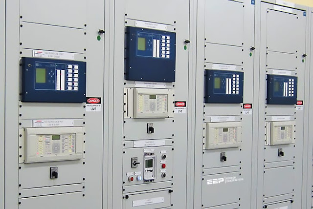
| Protection Relay Panel | Source |
Protective relaying is applied to components of a power system for the following reasons:
- Separate the faulted equipment from the remainder of the system so that the system can continue to function.
- Limit damage to the faulted equipment.
- Minimize the possibility of fire.
- Minimize hazards to personnel.
- Minimize the risk of damage to adjacent high-voltage apparatus.
Type of Transformer Failures
The electrical windings and the magnetic core in a transformer are subject to a number of different forces
during operation, for example
- Expansion and contraction due to thermal cycling
- Vibration
- Local heating due to magnetic flux
- Impact forces due to through-fault current
- Excessive heating due to overloading or inadequate cooling
Detection of Faults Using Fuse
Fuses are commonly used to provide fault detection for transformers with minimum nameplate ratings up to
5000 kVA, three-phase (Categories I and II). Transformers of 10 000 kVA and larger, three-phase, minimum
nameplate (Categories III and IV) are generally protected by a combination of protective devices.
Transformers that fall between these two ratings are protected by either fuses or relays. The
choice of protection depends on the criticality of the load, the relative size of the transformer compared to
the total system load, and potential safety concerns.
System considerations, such as coordinating fuses with
upstream relays or with transformer damage curves, may determine what protection is used. Some other
considerations include types of faults, personal safety issues, speed of clearing, single phasing of load, and
ferroresonance.
 |
| Transformer Protection for a Delta-Wye |
Fuses have the merits of being economical and requiring little maintenance.
Battery supply and a relay
building are not needed. Fuses can reliably protect some power transformers against damage from primary
and secondary external faults. They will provide limited protection for internal faults. Generally, more
sensitive means for protection from internal faults is provided for transformers of 10 MVA and higher. Fuses
have been used at higher transformer ratings, depending on the currently available fuse ampere ratings.
Primary fuses for power transformers are not applied for overload protection, their main purpose being fault
protection.
It should be recognized that the blowing of one fuse on a three-phase system will not
necessarily de-energize the fault. If the fault is not de-energized, the resulting single-phase service may be detrimental to the connected polyphase motors and other loads. If required, special protection should be
added for single-phase conditions.
A typical transformer that exhibits this protection shortfall is a ∆ primary, grounded T secondary distribution
station transformer that is protected with fuses on the primary side.
If a phase-to-phase-to-ground fault
occurs on the secondary side between the transformer terminals and the low-side protective device, then the
fault must be cleared by the high-side fuses. The fuse with the highest current will operate first, leaving the
transformer energized through the remaining two fuses. At this point, the secondary fault is further limited by
twice the transformer impedance, and, depending on the fuse size, transformer impedance, and system
impedance, the remaining fuses may or may not operate.
This condition could overload the transformer but
severely overloads the neutral connection because the currents in the secondary windings are in phase and
sum algebraically in the neutral connection.
The table below shows the magnitude of currents for a typical 69–
13.2 kV, 8.4 MVA distribution transformer before and after the first fuse clears.
This transformer would normally be protected by a 100E fuse. The table clearly shows that the current in the neutral connection remains
essentially the same after the first fuse opens and will persist until the second fuse opens.
 |
| Currents for a Typical Distribution Transformer |
The selection of the fuse and proper ampere rating should be based on the following factors:
- Hot load pickup (inrush current on instantaneous reclosing of source-side circuit breaker) and cold load pickup (inrush current and undiversified load current after an extended outage)
- Available primary system fault current and transformer impedance
- Fuse fault-interrupting capability and available system fault current
- Maximum allowable fault time on the low-side bus conductors
- Transformer connections and grounding impedance as affecting the primary current for various types of secondary faults
- Sensitivity for high-impedance faults
- Transformer magnetizing inrush
- The maximum anticipated peak load current, daily peak loads, emergency peak loads, maximum permissible transformer load current, and the applicable transformer through-fault current duration curve.
- Coordination with source-side protection equipment
- Coordination with low-side protection equipment
Reference:
- IEEE Guide for Protective Relay Applications to Power Transformers | Download
- Publisher: IEEE
- Committee: Sponsor Power Systems Relay Committee of the IEEE Power Engineering Society

.webp)


No comments: