Major Component of Large Generators
The components of the generator and excitation system are individual described in the following sections:
1. GENERATOR ENCLOSURE
The generator is a combination of three sections:
- Frame unit
- Exciter housing
- Cooler unit
- The frame unit consists of a steel frame that houses the stator core, the windings and the rotor. The lower section of the frame also accommodates the connection terminals.
- The exciter housing houses the brushless exciter. One duct on top of the exciter housing allows generator cooling air to flow into the exciter and cools down the exciter components.
- Cooler unit located on top of the generator frame unit accommodates the air coolers and water pipe connections.
- A door on the exciter housing allows inspection and maintenance of the exciter.
- All the above components are mounted on a common steel platform (bed) as a single unit. Lifting lugs are provided on each section to allow handling at the time of installation and transportation.
2. STATOR
- The stator core is a hollow cylinder formed by stacks of laminated, cold rolled silicon steel plates.
- The laminations are clamped by insulated bolts. The core has ventilation ducts that allow coolant air to flow through them.
- Full-length longitudinal slots, designed to accommodate the winding conductors, are provided on the inner periphery of the core.
- The stator core is supported within the frame by using a flexible mounting.
- This arrangement prevents the high level of vibration - usual in a 2-pole machine due to the magnetic forces - to be transferred to the frame and the foundation.
3. ROTOR
- Slots are cut along the full length of the rotor body to accommodate the field windings.
- The exciter side of the shaft has center bores, which allow the field winding leads to pass thru them for connection with the rotating rectifier (RR) of the brushless excitation system.
- Two axial blowers are mounted on the two ends of the generator rotor shaft.
- A fan guide is clamped to the stator which directs the air to flow into the blower.
- Retaining rings made of non-magnetic material are fitted with the winding end turns to support and protect the turns from being damaged by centrifugal forces which develop on a running generator.
- This also allows axial thermal expansion of the rotor winding.
- The generator field windings are connected with the RR of brushless excitation system by using two insulated conductors that pass through the hollow center bore of the rotor shaft.
4. OUTPUT TERMINALS
- Located at the lower part of the stator frame, and on the opposite side of the turbine, is the CT Trunk for making electrical output connections.
- The CT trunk houses the three leads for the generator three line terminals and the bushing CTs.
- The adaptor box connects the generator line terminals with the IPB to deliver the power.
- Three terminal leads are shorted after passing the bushing CT’s to form the neutral terminal and are connected to the generator neutral grounding equipment mounted in the cooler unit.
5. NEUTRAL GROUNDING EQUIPMENT
- The generator neutral is high impedance grounded via a transformer with a current limiting resistor on the secondary.
- The neutral grounding equipment (NGT) is mounted within the generator cooler unit together with the bushing CT’s on neutral leads.
6. COOLING SYSTEM
- The generator is internally cooled down by air.The air is circulated by two axial blowers (fans) mounted at both ends of the rotor shaft.The air enters from both ends of the generator, moves inside (through air gap and rotor axial ventilating slots) axially and then spreads in radial direction through the ventilating ducts in the core.
- The hot air from the stator passes through air coolers, which cools down the air and the cooled air is reused for next cycle cooling.A part of the cooling air also circulates over the brushless excitation system and neutral grounding equipment to cool them.
- The cooling water is supplied from the closed cycle cooling water system of the power station. Generator loading depends on the number of air coolers in operation.
7. BEARINGS
- Tilting pad type bearings with forced external oil supply are used in the generator.The bearings at each location are arranged in two halves: upper and lower.The bearings are insulated to prevent eddy currents, generated in the shaft, from passing between the shaft and the bearings that could otherwise damage the bearings.
- While the upper half is insulated with a bearing keeper, the lower half uses an insulating sheet, between the bearing ring and the bearing fit surface, fastened by insulated bolts.
- Insulating materials are inserted into the other parts such as between oil seal and bracket, to prevent shaft current from flowing through these areas.
8. EXCITER
The typical brushless excitation system for large generator consists of the following:
- A permanent magnet type generator (PMG)- An AC exciter- Rotating rectifier (RR)- AVR
9. ANTI CONDENSATION HEATER
- Anti-condensation space heaters are installed at the bottom side of the generator stator frame.
- In the exciter housing, the space heaters are mounted on the wall inside of exciter housing.
10. GENERATOR CONTROL PANEL(GCP)
- Generator control panels (GCP) are installed in the T/G control room to allow local synchronization of generator, AVR mode of operation selection.
11. GENERATOR MAIN CIRCUIT BREAKER
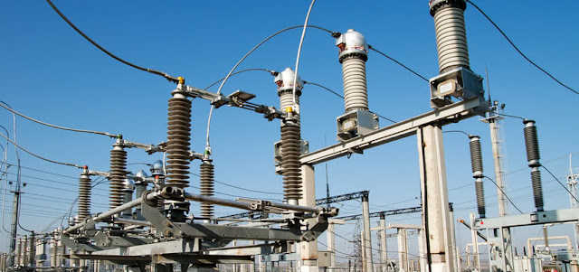
- The GMCB system is housed in a composite cubicle unit consisting of SF6 circuit breaker, disconnecting switches, earth switches.
- The generator circuit breaker is SF6 type, naturally cooled and hydraulically operated.
- The SF6 gas is filled in bus tanks and insulating tubes, which are arranged horizontally on frame and insulated from the ground by supporting insulator. Dual flow puffer type interrupters are used in the circuit breaker.
12. ISOLATED PHASE BUSDUCT (IPB)
- IPB is used to make connection between the line terminals of the generator and the low voltage terminals (16.5kV) of the generator transformer.
- IPB carries the output power from the three phase terminals of the generator and delivers the power at the terminals of the generator transformer, which then steps up the voltage for delivering to the high voltage transmission systems.
13. TAP CHANGER CONTROL
Generator transformer tap position may need to be raised and lowered to:
- Regulate the reactive power (VAR) flow between the generator and the grid.Raise/lower the voltage on the HV side of the transformer voltage when the transformer is already energized on its LV side.
- Raise/lower the voltage on the LV side of the transformer when the transformer is energized from the HV side and not on the LV side.


.webp)


No comments: