Design Guide: Resistance Grounding In Electrical System
What is a resistance grounding?
Resistance grounding in an electrical system is defined as the use of a resistor as a grounding path between the neutral point of transformer or generator and the earth ground. There are two methods to accomplish this system of grounding, namely the low resistance grounding and high resistance grounding.
IEEE Standard 142-1991 states that the reasons for limiting the current by resistance grounding may be one or more of the following:
Low resistance grounding limits the ground fault current to a minimum value of 50 amperes. The reason for having this value is to quickly clear the fault (usually within a few seconds).
Purpose:
IEEE Standard 142-1991 defnes High Resistance Grounded System as follows:
High resistance grounding solves the problem of transient over-voltages, thereby reducing equipment damage. This is to industrial plants where the connected loads are very sensitive.
Characteristics:
Ohms law (R = V / I) state that if we know the phase to ground voltage and the desired current we can directly compute for the grounding resistance. But in case of grounding resistance we need to consider the line to ground capacitance that the system has. This capacitance determines the magnitude of zero sequence charging current. Therefore we need to know first the charging current of the capacitance developed between phase to ground and we will determine the resistor calculation thereafter.
Determining the capacitive charging current
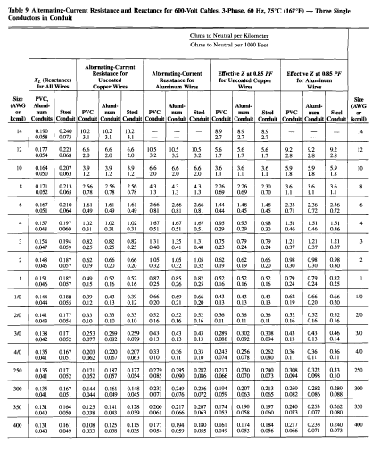
As describe in the above diagram, while there is no physical capacitance present in the circuit however there is a large value of current that is being expected during the fault condition, that is why we will not disregard the same. For convenience we will use the typical charging current table, viz:
With the resistance set for the maximum, the current should be limited to the half the estimated charging current.
Three Phase Formula: Rmax = 2VL / [ sqrt(3) x 3 Ico]
Example:
An electrical system with installed capacity of 5 MVA has a system voltage of 13, 800 Volts. Determine the maximum value of grounding resistor?
Solution:
Referring to the table above @ 13,800 Volts and 5 MVA (5,000 KVA), 3 Ico = 50 Amps
Therefore:
Rmax = 2VL / [ sqrt(3) x 3 Ico]
R max = 2 x (13,800) / (1.73 x 50)
R max = 319 ohms
Summary:
Resistance grounding in an electrical system is defined as the use of a resistor as a grounding path between the neutral point of transformer or generator and the earth ground. There are two methods to accomplish this system of grounding, namely the low resistance grounding and high resistance grounding.
IEEE Standard 142-1991 states that the reasons for limiting the current by resistance grounding may be one or more of the following:
- To reduce the burning and melting effects in faulted electrical equipment such as switchgears, transformers, cables and rotating machines.
- To reduce the mechanical stress in circuits and apparatus carrying fault currents.
- To reduce electrical shock hazards to personnel caused by stray ground fault currents in the ground return path.
- To reduce arc blast or flash hazard to personnel who may have accidentally caused or who happen to be close proximity to the ground fault.
- To reduce the momentary line voltage dip occasioned by the occurrence and clearing of a ground fault.
- To secure control of the transient over voltages while the same time avoiding the shutdown of a facility circuit on the occurrence of the first ground fault (high resistance grounding).
Low resistance grounding limits the ground fault current to a minimum value of 50 amperes. The reason for having this value is to quickly clear the fault (usually within a few seconds).
Purpose:
- Limit the damage to the equipment
- Prevent additional faults from occurring
- Provides safety to personnel
- Localizes the fault
- Limits phase to ground currents to 50 ampere to 400 ampere.
- Reduces arcing current and eliminates arc flash hazards associated with phase to ground arcing current conditions.
- Limit the mechanical damage and thermal damage to shorted transformer and rotating machinery windings.
- Does not prevent operation of over current devices.
- Does not require a ground fault detection system.
- Conductor insulation and surge arresters must be rated based on the line-to-line voltage. Phase to neutral loads must be served through an isolation transformer.
IEEE Standard 142-1991 defnes High Resistance Grounded System as follows:
A grounded system with a purposely inserted resistance that limits ground fault current can flow for an extended period without exacerbating damage. This level of current is commonly thought to be a 10 A or less. High resistance grounded systems are designed to meet the criteria R0 < = Xco to limit the transient over-current voltages due to arcing ground faults. Ro is the per phase zero sequence resistance of the system and Xco is the distributed per phase capacitive reactance-to-ground of the system.Purpose:
High resistance grounding solves the problem of transient over-voltages, thereby reducing equipment damage. This is to industrial plants where the connected loads are very sensitive.
Characteristics:
- Limit phase to ground currents to 5-10 ampere.
- Reduces arcing current and eliminates arc flash hazards associated with phase to ground arcing current conditions.
- Eliminate the mechanical damage and may limit thermal damage to shorted transformer and rotating machinery windings.
- Prevents operation and overcurrent devices until the fault can be located.
- Requires a ground fault detection system to notify the facility engineer that a ground fault condition has occurred.
- Conductor insulation and surge arresters must be rated based on the line-to-line voltage. Phase to neutral loads must be served through an isolation transformer.
Ohms law (R = V / I) state that if we know the phase to ground voltage and the desired current we can directly compute for the grounding resistance. But in case of grounding resistance we need to consider the line to ground capacitance that the system has. This capacitance determines the magnitude of zero sequence charging current. Therefore we need to know first the charging current of the capacitance developed between phase to ground and we will determine the resistor calculation thereafter.
Determining the capacitive charging current
 |
| Schematic and Phasor Diagram of Capacitance Charging Current |
As describe in the above diagram, while there is no physical capacitance present in the circuit however there is a large value of current that is being expected during the fault condition, that is why we will not disregard the same. For convenience we will use the typical charging current table, viz:
 |
| Typical Charging Current |
With the resistance set for the maximum, the current should be limited to the half the estimated charging current.
Three Phase Formula: Rmax = 2VL / [ sqrt(3) x 3 Ico]
Example:
An electrical system with installed capacity of 5 MVA has a system voltage of 13, 800 Volts. Determine the maximum value of grounding resistor?
Solution:
Referring to the table above @ 13,800 Volts and 5 MVA (5,000 KVA), 3 Ico = 50 Amps
Therefore:
Rmax = 2VL / [ sqrt(3) x 3 Ico]
R max = 2 x (13,800) / (1.73 x 50)
R max = 319 ohms
Summary:
- Resistance Grounding Systems have many advantages over solidly groundedsystems including arc-flash hazard reduction, limiting mechanical and thermaldamage associated with faults, and controlling transient overvoltages.
- High resistance grounding systems may also be employed to maintain service continuity and assist with locating the source of a fault.
- When designing a system with resistors, the design/consulting engineer mustconsider the specific requirements for conductor insulation ratings, surge arrestorratings, breaker single-pole duty ratings, and method of serving phase-to-neutral loads.
- Ground Fault Protection Technical Guide, Post Glover Resistors
- Resistance Grounding System Basics, General Electric
- National Electric Code

.webp)


Do not allow open flames and smoking in all such areas where inflammable liquids or gases are stored or being used. Used Lab Equipment For Sale
ReplyDeleteNice blog… Thanks for sharing very useful information about electrical circuits.
ReplyDeleteDesigning Electrical Circuits
Thanks for the informative explanation! Resistance grounding plays a crucial role in electrical systems by mitigating various risks and Invisible Text hazards. Understanding its methods and purposes is essential for safe operation.
ReplyDeleteIncorporating resistance training into your routine builds strength and tones muscles. A great way to challenge yourself!Ama1gear
ReplyDeleteFeel the rhythm of the water as you paddle through calm or rough waters.durable basketballs for indoor and outdoor use
ReplyDeleteAwesome work thanks for sharing this Kennedy Funding Ripoff Report with us.
ReplyDeleteThanks for this detailed guide on resistance grounding. The comparison between low and high resistance systems, especially the sizing calculations, is very practical for electrical design. For those looking to create unique diagrams or stylized headers for their technical documentation, tools like Font Generator and Glitch Text are great resources to explore. Appreciate the share!
ReplyDelete