Voltage Drop Calculation Based on National Electrical Code
Calculating voltage drop is very important in every electrical design especially when we are dealing with sensitive loads. Failure to calculate the voltage drop properly will result to under-voltage at the receiving end of the system. And undervoltage could lead into inefficient performance of our equipment. The allowable range can be found in NFPA 70, the National Electrical Code (NEC). The National Electrical Code (NEC) establishes criteria for the maximum permitted voltage drop in a circuit, which is typically 3% for branch circuits and 5% for feeder circuits. These guidelines apply to branch circuits and feeder circuits, respectively. If the voltage drop in a circuit exceeds these limitations, it can cause problems such as poor performance of electrical equipment and higher energy consumption. These limits have been established to prevent problems like these from occurring. Electricians and engineers are able to confirm that the designs and installations of circuits comply with the NEC, that the circuits will function correctly and effectively, and that these assurances may be achieved by completing voltage drop calculations.
Voltage drop occurs when electrical current flows through a conductor, such as a wire. As the current flows, it generates resistance, which causes the voltage to decrease. The longer the conductor or the larger the current, the greater the voltage drop will be.
If the voltage drop is too high, it can cause the devices and equipment connected to the circuit to malfunction or fail. For example, if the voltage drop is too high in a lighting circuit, the lights may be dim or flicker. In an industrial setting, high voltage drop can cause motors to overheat or stall, which can lead to equipment failure and downtime.
To ensure that voltage drop is within acceptable limits, electrical engineers and designers use calculations to determine the amount of voltage drop that will occur in a circuit. This is typically done by using the National Electric Code (NEC) guidelines, which provide formulas and tables to calculate voltage drop based on the type and size of conductor, the length of the circuit, and the amount of current flowing through the circuit.
By calculating voltage drop, engineers and designers can make sure that the voltage at the end of the circuit is sufficient to operate the devices and equipment connected to it. It also helps to identify potential issues before they occur and to design the circuit to minimize the potential for voltage drop.
Voltage drop formula:
- Vd = ( 2 x Z x I x L )/ 1000 ---> for single phase system
- Vd = ( 1.73 x Z x I x L) / 1000 ---> for three phase system
where:
Vd = voltage drop
Z = impedance of the conductor per 1000 ft. (see NEC chapter 9 table 8 or 9)
I = load current in amperes
L = length in feet
1000 = constant to compensate with "per 1000 ft" in impedance value.
The National Electrical Code chapter 9 provides conductor properties based on 75 deg.C installations. Therefore for installations higher than above mentioned value we are required to consider special calculation procedure which is to be discuss in other article.
Table 8 refers to direct current system while table 9 refers to alternating current system. But there are important considerations in using this NEC table 8 and 9, viz:
- Use Table 8 for conductor sizes up to #4/0 since in this sizes R is approximately equal to Z
- Use Table 9 for conductor sizes higher that #4/0
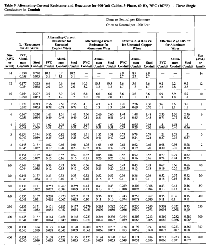
 |
| NEC Chapter 9 Table 9 |
Example:
A 10 HP motor is to be installed in a 220 V, 3-phase AC system. If the motor is located at 300 feet from the source, calculate its voltage drop?
Solution:
There are three approach in getting the current drawn of any motor.
- Nameplate Rating
- NEC given value
- Conventional Calculation
For the sake of discussion we will take the third method by assuming power factor and efficiency of the motor to be 80%.
I = (20 HP x 745 W) / (1.73 x 220 x 0.80 x 0.80)
I = 61.25 Amperes ---> full load ampres (FLA)
NEC provides that the the conductor must not be lesser than 125% of the motor's FLA.This value, 76.6 amperes will the basis of our voltage drop calculation.
- Therefore: I = 56.0 x 1.25 = 76.6 Amperes
- NEC table of conductor ampacities provides that at 76.6 amperes wire size must be #4 copper based on NEC Art 310
note: the voltage drop calculation should be taken after we get the 125% safety factor provided by the NEC.
It follows that,
Vd= (1.73 x Z of #4 x 76.6 x 300 ft. )/ 1000
Based on NEC Chapter 9 Table 9,
- Z = 0.321 ohm/ 1000 ft
- Therefore: Vd = (1.73 x 0.321 x 76.6 x 300) /1000
- Vd = 12.76 Volts
It follows that, %Vd = 12.76 V / 240 V = 5.3%
The NEC recommends that 5% voltage drop percentage is allowable in any circuit installation so if we strictly follow this recommendation then we will not accept #4 conductor but rather we will move up to the next higher size.
In summary, calculating voltage drop is important because it helps to ensure that the voltage at the end of a circuit is sufficient to operate the devices and equipment connected to it and prevents equipment failure, downtime, and other problems that can result from high voltage drop.

.webp)


Furthermore, by varying the current setting and the restraint on the movable element, Used Lab Equipment Distributors
ReplyDelete...and the 10 HP motor in the problem statement somehow turns in to a 20HP motor. It don't hurt to revise your work before publishing
ReplyDeleteThe size of the branch circuit protection for motor loads shall not be greater than 250% of motor full load current for CB and 300% for non-time delay fuses on full voltage starting. CCTV Installers Melbourne
ReplyDeletethe voltage at each heap might be not exactly expected because of current move through the basic impedances (R, for example, the test leads and follow obstruction. high voltage resistor manufacturer
ReplyDeleteBe that as it may, the Farad all alone is a very enormous unit so sub-units of the Farad are generally utilized like miniature farads (uF), nano-farads (nF) and pico-farads (pF) to mean a capacitors esteem.
ReplyDeleteChina mosfet manufacturer
The purpose of the National Electrical Code is the practical safeguarding of persons and property from hazards arising by the use of electricity. about us
ReplyDeleteHow do you calculate voltage drop in NEC?
ReplyDeleteURL: https://www.affordablelectricians.com.au/electrician-mitcham.html
Decreasing conductor temperature. Allowable Voltage Drop According to the NEC, 2011 Edition. contact us
ReplyDeleteThanks for the blog loaded with so many information. Stopping by your blog helped me to get what I was looking for. 2cl2fl
ReplyDeleteThanks for the table and calculation formulas that you have provided, this is really great work done by you.
ReplyDeleteCable sizing calculator australia
Voltage drop calculation is something not anyone can pull off. Consider hiring electrician for such tasks.
ReplyDeletewww.electriciansouthauckland.kiwi/
The calculation of voltage drop should be left to the professionals. Great post by the way. our website
ReplyDeleteIt's also great that you included the formula for people to follow. Much appreciated! electricianswindsor.ca
ReplyDeleteIt is what I was looking for and is interesting. It is a consideration as well as a useful write-up for us. Thankful to you for sharing a post similar to this. Electrical Enclosures
ReplyDelete